2OM-1064-002.pdf - 第77页
H (mm) Set the component placement height. A parameter can be set for each pattern. C Control commands can be set. “-” : This command specifies the steps as those for repetitive placement. “S” : This command invalidates …
Description of Parameters
O-NO
This shows the step Nos. of repetitive placement data.
(The step “O-0000” always appears on the screen.)
• Enter “0” (zero) in all data fields and “-” as a control command in step
“O-0000”.
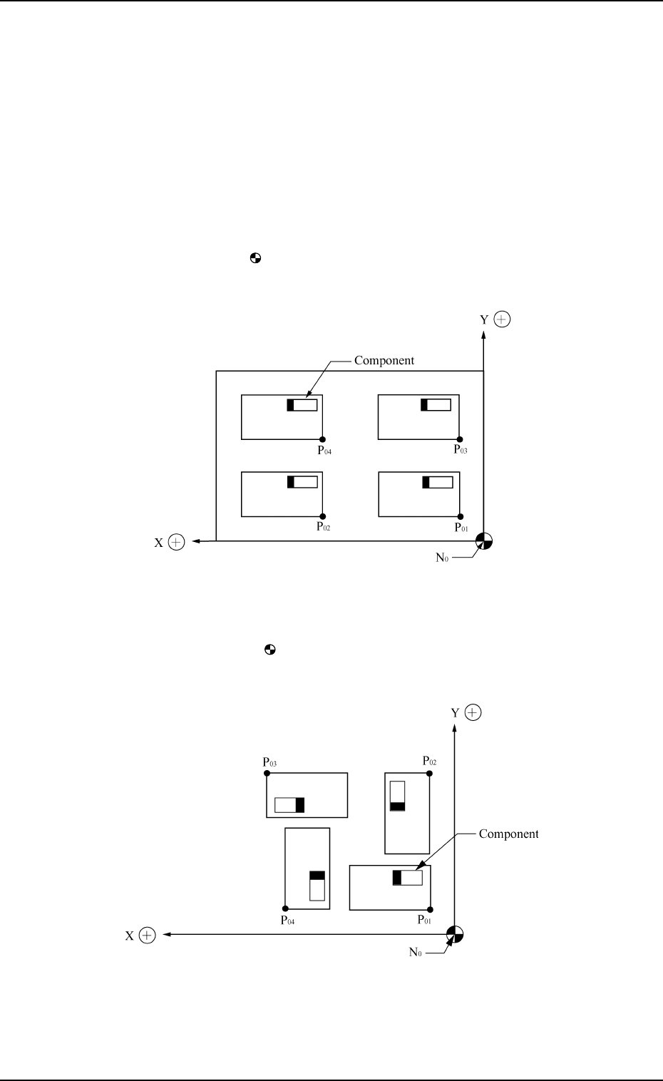
X (mm) and Y (mm)
Set the coordinates (X and Y) from the placement data reference to the
origin for each pattern.
Ref.: The pattern origin refers to the coordinates for the multi-unit P.C.B.
which forms repetitive patterns.
N
0
: The center of mark is Placement Data Reference.
P
01
: Pattern Origin of Pattern 1
P
02
: Pattern Origin of Pattern 2
P
03
: Pattern Origin of Pattern 3
P
04
: Pattern Origin of Pattern 4
Pattern 1: 0°
Pattern 2: 90°
Pattern 3: 180°
Pattern 4: 270°
N
0
: The center of mark is Placement Data Reference.
P
01
: Pattern Origin of Pattern 1
P
02
: Pattern Origin of Pattern 2
P
03
: Pattern Origin of Pattern 3
P
04
: Pattern Origin of Pattern 4
0004-002 2-64 Tg0247-PM-PM
2. Pattern Program
Z=THETA (Angle)
Set the angle of each pattern.
• 0°, 90°, 180°, or 270° can be set as a parameter.

H (mm)
Set the component placement height.
A parameter can be set for each pattern.
C
Control commands can be set.
“-” : This command specifies the steps as those for repetitive placement.
“S” : This command invalidates the steps specified as those for repetitive
placement data, bypassing the specified steps.
“C” : This command invalidates the steps specified as repetitive placement
data (only the component placement machine).
“D” : This command handles the steps as those used for repetitive place-
ment.
(Step invalidating command for a glue dispenser)
“E” : This command shows the end of repetitive placement data (O).
Note : Positional offset data is not valid in the steps where a control com-
mand other than “-” and “D” is entered.
(Including indefinite commands other than the above-described
ones)
COMMENT
A comment can be entered for each step No.
Up to 8 characters can be entered.
Any operation is not affected by the comment.
0004-002 2-65 Tg0247-PM-PM
2. Pattern Program
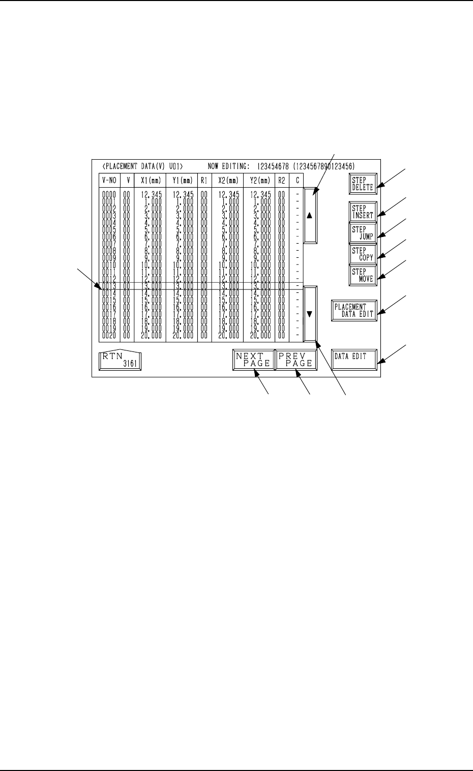
2.6.4 PLACEMENT DATA (V) Display [P.E.C. Data for Each Repeti-
tive Pattern]
When the [VISION DATA EDIT] key is pressed a the “PLACMENT DATA
(P) U01” display (Fig. 2.45-1 or Fig. 2.45-2), the following display appears on
the screen.
A list of P.E.C. data for each repetitive pattern is displayed.
Parameters can be edited at the display opened by pressing the [DATA EDIT]
key *13.
*2
*8
*9
*10
*12
*11
*16
*13
*3
*5
*4
*1
2. Pattern Program
9910-001 2-66 Tg0247-PM-PM
Fig. 2.48
Description of Parameters
V-NO
This shows the step Nos. of the placement data (V).
(Only V-0000 is used.)
V
[Setting of Repetitive Patterns]
When multi-unit P.C.B.’s (repetitive patterns) are used and the P.E.C. func-
tion is implemented, set “02” in the text field labeled “V” of the V-0000
step.
00: B.B.R. P.E.C. Recognition Function “OFF”
01: B.B.R. P.E.C. Recognition Function “ON” (1-Point Recognition)
02: B.B.R. P.E.C. Recognition Function “ON” (2-Point Recognition)
Ref.: As both V data shown at the placement data (V) and (P) displays
are the same, the V data can be entered at either display.
[Setting of Each Individual Placement Points]
Set each individual placement points in the text field labeled “V” of the
placement step.
00: P.E.C. Recognition “OFF”
01: P.E.C. Recognition “ON” (1-Point Recognition)
02: P.E.C. Recognition “ON” (2-Point Recognition)
Note: Set “ON” in the “P.E.C. RECOGNITION” data box and in the “LO-
CAL” data box of the label “P.E.C. RECOGNITION MODE” at the
“OPERATION DATA” display.