2OM-1064-002.pdf - 第47页
9910-001 2-35 Tg0247-PM-PM 2. Pattern Program *1 The line cursor (blue) is used to select a step. The line cursor can be moved up or down by pressing the [ ] or the [ ] key . *2 [ ] Key Press this key to move the line cu…
[SCREENS] Key
Fig. 2.31
*1
*6
*7
*2
*3
*10
*11
*9
*4 *5
*8
Fig. 2.31-1
Fig. 2.31-2
2. Pattern Program
9910-001 2-34 Tg0247-PM-PM
[TAPE A]
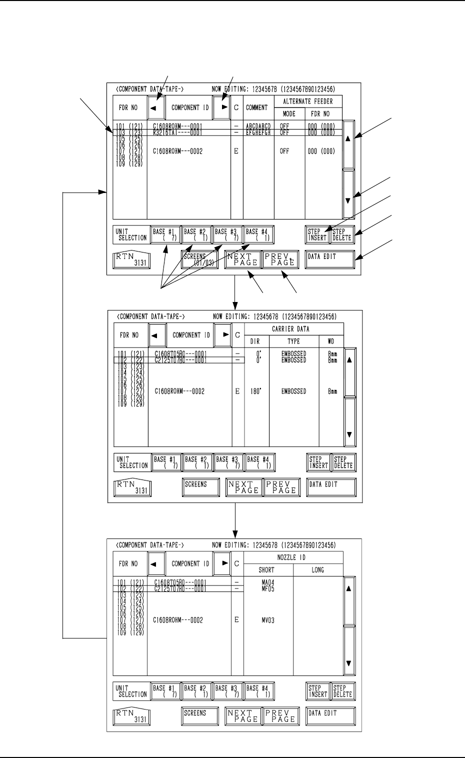
Every time the [SCREENS] key is pressed at the display (Fig. 2.31), another
display appears on the screen.

9910-001 2-35 Tg0247-PM-PM
2. Pattern Program
*1 The line cursor (blue) is used to select a step.
The line cursor can be moved up or down by pressing the [ ] or the [ ] key.
*2 [ ] Key
Press this key to move the line cursor upward.
When the line cursor is located at the top and this key is pressed, feeder
Nos. (FDR NO) scroll up. (Smaller Nos. appear one by one.)
*3 [ ] Key
Press this key to move the line cursor downward.
When the line cursor is located at the bottom and this key is pressed,
feeder Nos. (FDR NO) scroll down. (Larger Nos. appear one by one.)
*4 [NEXT PAGE] Key
Pressing this key opens the next page.
*5 [PREV. PAGE] Key
Pressing this key opens the previous page.
*6 [ ] Key
Pressing this key shifts the “COMPONENT ID” field horizontally to the
left, enabling to view the first part of component IDs.
*7 [ ] Key
Pressing this key shifts the “COMPONENT ID” field horizontally to the
right, enabling to view the comments (comments entered in the compo-
nent library).
*8 UNIT SELECTION [BASE #1], [BASE #2], [BASE #3],
and [BASE #4] Keys
When one of these keys is pressed, the component data related to the se-
lected feeder base unit appears on the screen.
When parameters are set in the component data, the background color is
turned green.
The numbers in ( ) show the step count of registered feeder Nos.
*9 [STEP INSERT] Key
When this key is pressed, a blank lane of 1 pitch is inserted (registered) in
the feeder No. at the line cursor position.
Note: Shown below are the maximum number of units to be set for each
individual feeder.
• Tape Feeder: Max. 19
• Vibratory Stick Feeder: Max. 9
(The maximum number may decrease, depending on the stick
size.)
• Multi-Layer Tray Feeder (Option): Max. 99
Example: When the line cursor is located at FDR NO 102 at the dis-
play (Fig. 2.31-1) and this key is pressed, a blank lane is
inserted as follows.
FDR NO. COMPONENT ID
101(121) C1608T05B0 - - - 0001
102(122)
103(123) C2125T07B0 - - - 0001
104(124)
·
·
·
•
The feeder Nos. subsequent to the inserted one are shifted by 1 pitch.
*10 [STEP DELETE] Key
When the line cursor is moved to the feeder No. to be deleted and this key
is pressed, the data related to the feeder No. is deleted.
(The line at the line cursor position is deleted and the subsequent data is
shifted up.)
*11 [DATA EDIT] Key
When this key is pressed, a component data edit display opens.
A blank lane is inserted.
2. Pattern Program
9910-001 2-36 Tg0247-PM-PM