2OM-1064-002.pdf - 第179页
Second Page FEEDER BASE OFFSET X (mm), Y (mm) The set offset parameters are used to adjust the positional de- viations based on the design dimensions of Feeder Bases #1, #2, #3, and #4 (#1 and #2 on Side A, #3 and #4 on …
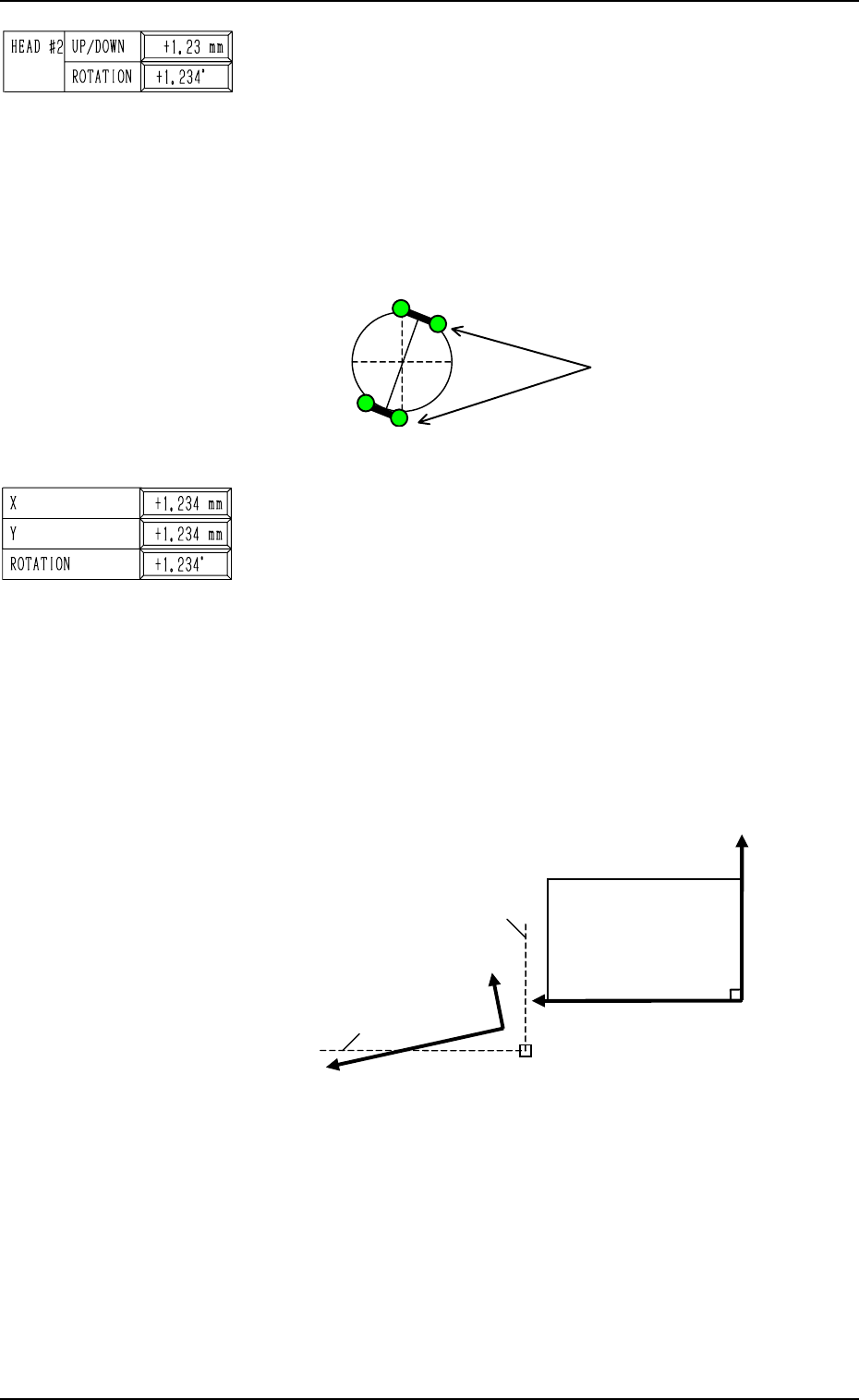
Fig. 5.5
BEAM B X (Horizontal), Y (Vertical), ROTATION
The set offset data is used to adjust the positional and angular
deviations based on the design dimensions representing the
beam B driving X/Y coordinates (BeamB-X/Y: Origin B0)
viewed from the P.C.B. positioning X/Y coordinates (PL-XY:
Origin P0). The values based on the PL-X and PL-Y coordi-
nates must be entered in the data boxes.
• Design Values (X: +554.000 mm, Y: -130.000 mm)
Origin B
0
is the scanning coordinate center of the P.E.C.
camera installed on Beam B when Beam-B X/Y axis are
located at their origins.
This offset data is automatically calculated through teach-
ing operation which is performed, using a jig P.C.B.
BEAM A/BEAM B HEAD #1/HEAD #2 ROTATION
This offset data (offset data for the origin positions of the head
rotational axis) is used to adjust the directions of the nozzle
clamp levers when the nozzles must be rotated for replace-
ment.
When the head rotational axis is zeroed and the nozzle clamp
levers face the directions shown in the figure below, a plus
parameter must be entered as the offset data.
When the rotational axis is zeroed, the nozzle clamp levers are
designed to face the “12 o’clock” and “6 o’clock” directions.
9910-001 5-8 Tg0247-PM-PM
2. DEVICE OFFSET Display
Fig. 5.6
When the beam B driving X/Y coordinates (actual values) are
those as shown above, the offset parameters representing the
X (horizontal) and Y (vertical) values must be provided with
minus (-) signs and the offset parameter representing the rota-
tion (angle) with a plus (+) sign.
Nozzle Clamp Levers
Beam B Origin Position (Design Value): B0
BeamA-X (+) [Design Value]
BeamB-Y (+) [Design Value]
BeamB-X (+) [Actual Value]
BeamA-Y (+) [Actual Value]
P0
PL-X (+)
P.C.B. Positioning X/Y
Coordinates
PL-XY
PL-Y (+)
(Front Side of Machine)
Top View (based on the reference point “R- FRONT”)
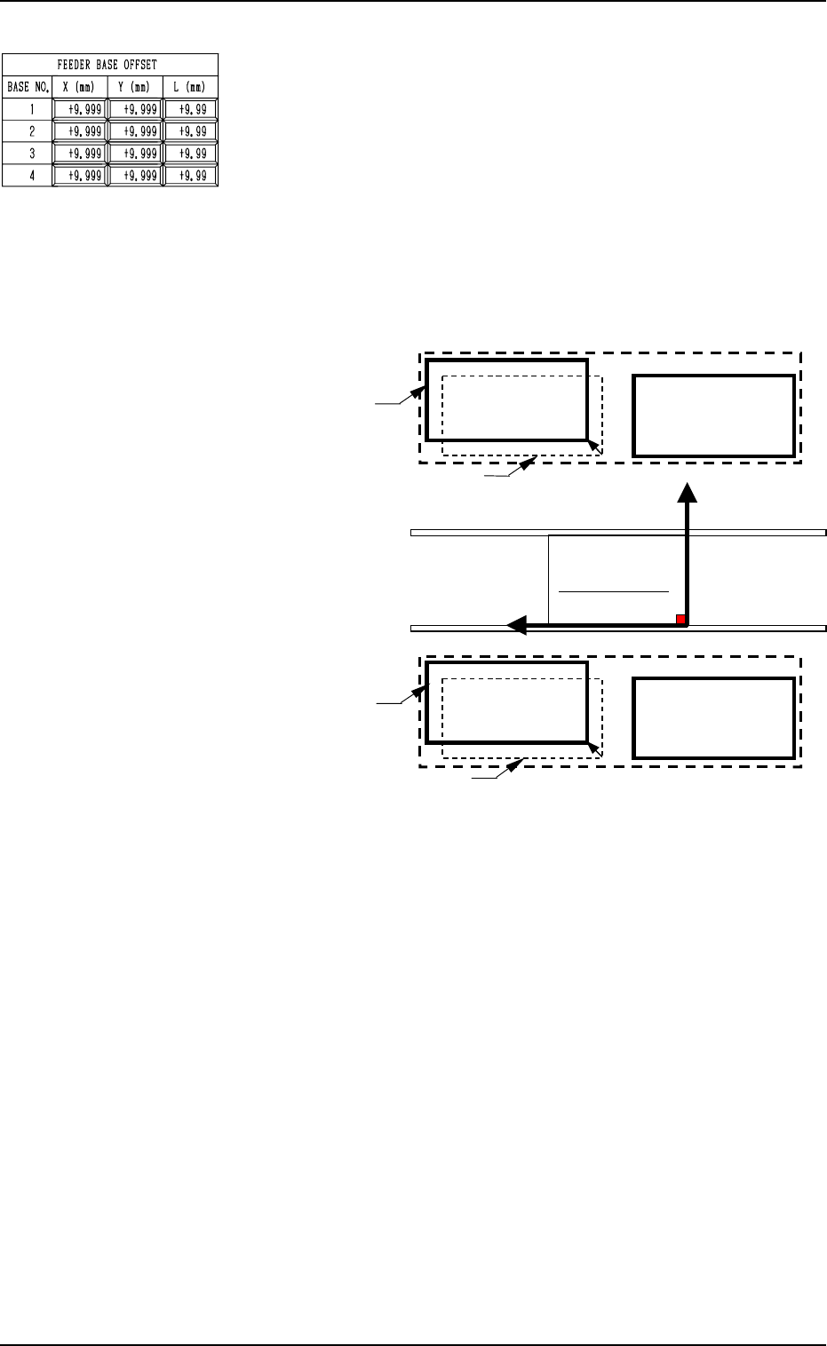
Second Page
FEEDER BASE OFFSET X (mm), Y (mm)
The set offset parameters are used to adjust the positional de-
viations based on the design dimensions of Feeder Bases #1,
#2, #3, and #4 (#1 and #2 on Side A, #3 and #4 on Side B).
The values based on the PL-XY coordinate system must be
entered in the data boxes.
Ref.: The manual alignment teaching operation is possible.
When Feeder Bases #1 and #4 are located as shown below, the
offset parameters are entered with “+” (plus) signs for both “X
(mm)” and “Y (mm)”.
9910-001 5-9 Tg0247-PM-PM
2. DEVICE OFFSET Display
PO
Y(+)
Y(+)Y(+)
Y(+)
X
XX
X (+)
(+)(+)
(+)
Feeder Base #1
Feeder Base #2
Feeder Base #3
Feeder Base #4
Actual Location of Feeder Base #1
Design Location of Feeder Base #1
Actual Location of Feeder Base #4
Design Location of Feeder Base #4
PL-XY Coordinate System
Feeder Base B
Feeder Base A
(Front Side of Machine)
Fig. 5.7
FEEDER BASE OFFSET L (mm)
The set offset parameters are used to adjust the vertical (height
direction) deviations based on the design dimensions of Feeder
Bases #1, #2, #3, and #4 (#1 and #2 on Side A, #3 and #4 on
Side B).
When a feeder base is installed lower than the design value,
plus values must be entered.
Ref.: When the [TEACHING] key *1 is pressed, the “UNIT
MANUAL ALIGNMENT TEACH” display appears
on the screen.
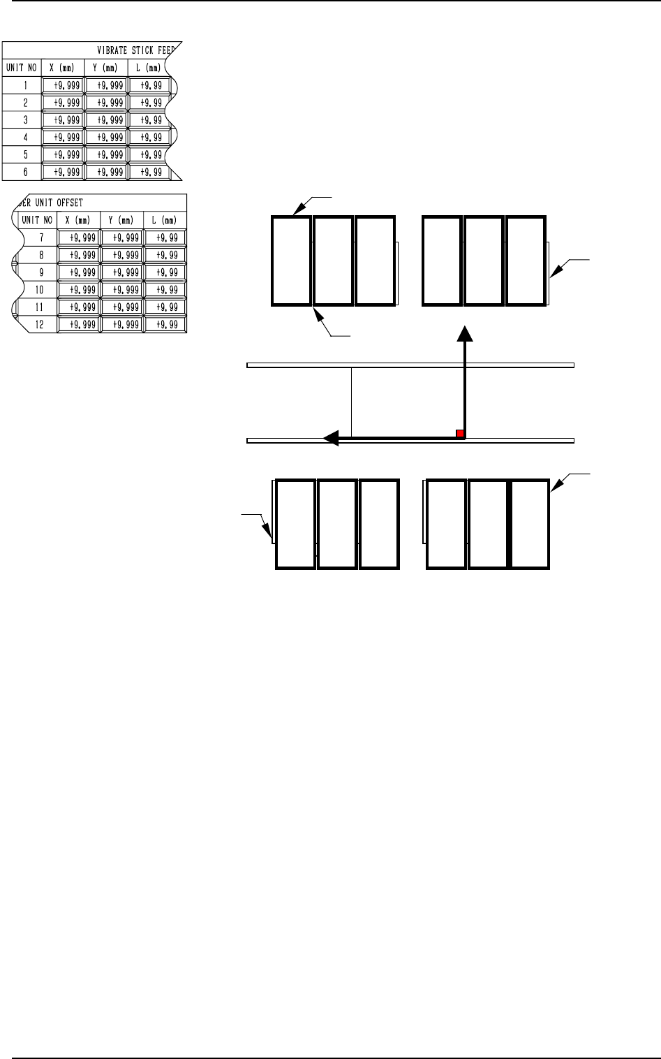
Third Page
VIBRATE STICK FEEDER UNIT OFFSET X (mm), Y (mm)
The set offset parameters are used to adjust the positional de-
viations based on the design dimensions of Vibratory Stick
Feeder Units #1 through #12 (#4 through #12 are optional).
The values based on the PL-XY coordinate system must be
entered in the data boxes.
Ref.: The manual alignment teaching operation is possible.
0004-002 5-10 Tg0247-PM-PM
2. DEVICE OFFSET Display
P0
Y(+)
X
(+)
PL-XY Coordinate System
Feeder Base #2
Feeder Base #3
Feeder Base #4
(Front Side of Machine)
12
3
45
6
12 11
10
9
8
7
Vibratory Stick Feeder Units
Feeder Base #1
Fig. 5.8
When offset parameters are entered with “+” (plus) signs for
“X (mm)” and “Y (mm)”, the X/Y head moves in the (+) di-
rection in the PL-XY coordinate system.
VIBRATE STICK FEEDER UNIT OFFSET L (mm)
The set offset parameters are used to adjust the vertical (height
direction) deviations based on the design dimensions of Vi-
bratory Stick Feeder Units #1 through #12 (#4 through #12
are optional).
When a vibratory stick feeder unit is installed lower than the
design value, plus values must be entered.
Ref.: When the [TEACHING] key *1 is pressed, the “UNIT
MANUAL ALIGNMENT TEACH” display appears
on the screen.