2OM-1064-002.pdf - 第78页
2.6.4 PLACEMENT DA T A (V) Display [P .E.C. Data for Each Repeti- tive Pattern] When the [VISION DA T A EDIT] key is pressed a the “PLACMENT DA T A (P) U01” display (Fig. 2.45-1 or Fig. 2.45-2), the following display app…

H (mm)
Set the component placement height.
A parameter can be set for each pattern.
C
Control commands can be set.
“-” : This command specifies the steps as those for repetitive placement.
“S” : This command invalidates the steps specified as those for repetitive
placement data, bypassing the specified steps.
“C” : This command invalidates the steps specified as repetitive placement
data (only the component placement machine).
“D” : This command handles the steps as those used for repetitive place-
ment.
(Step invalidating command for a glue dispenser)
“E” : This command shows the end of repetitive placement data (O).
Note : Positional offset data is not valid in the steps where a control com-
mand other than “-” and “D” is entered.
(Including indefinite commands other than the above-described
ones)
COMMENT
A comment can be entered for each step No.
Up to 8 characters can be entered.
Any operation is not affected by the comment.
0004-002 2-65 Tg0247-PM-PM
2. Pattern Program
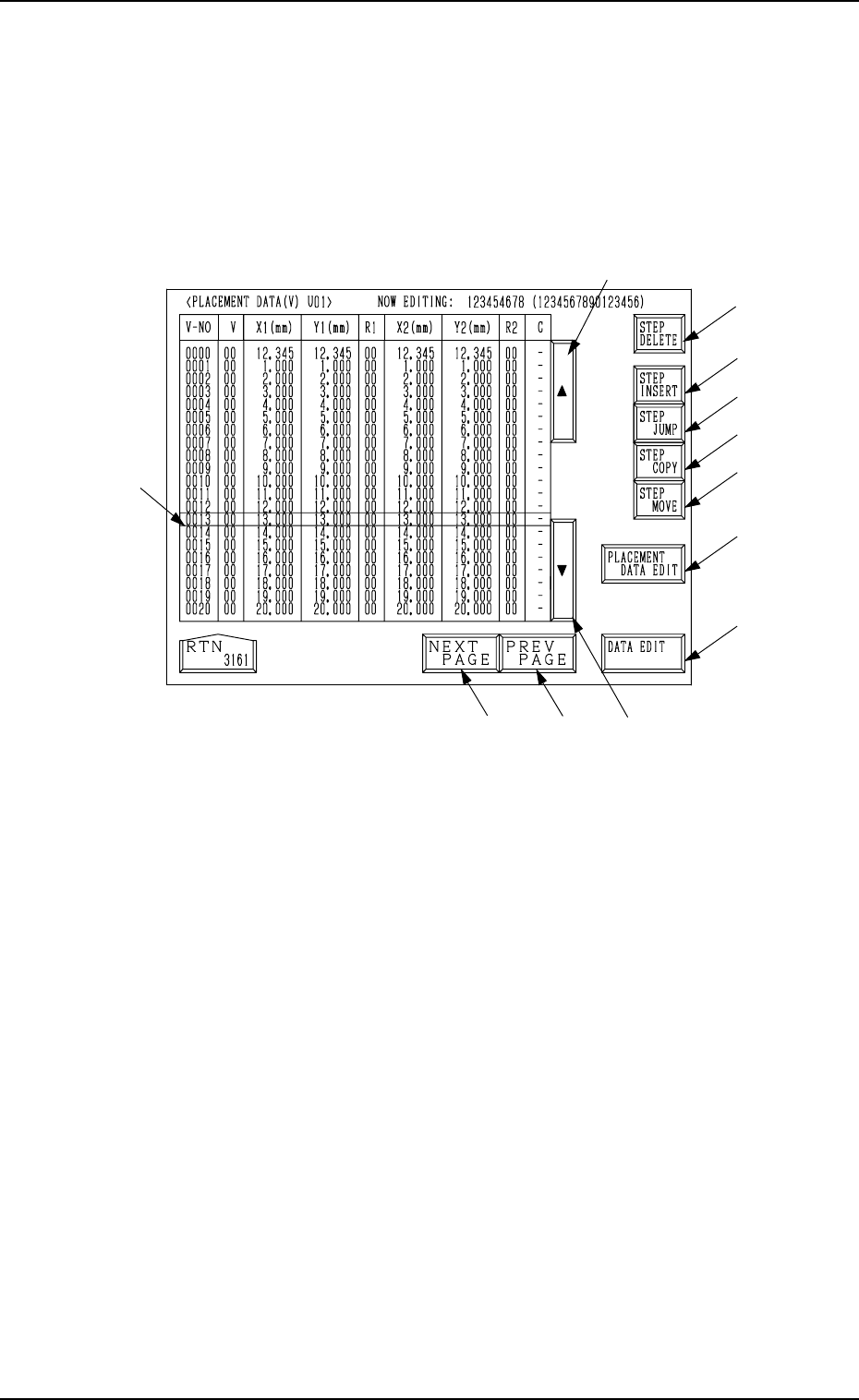
2.6.4 PLACEMENT DATA (V) Display [P.E.C. Data for Each Repeti-
tive Pattern]
When the [VISION DATA EDIT] key is pressed a the “PLACMENT DATA
(P) U01” display (Fig. 2.45-1 or Fig. 2.45-2), the following display appears on
the screen.
A list of P.E.C. data for each repetitive pattern is displayed.
Parameters can be edited at the display opened by pressing the [DATA EDIT]
key *13.
*2
*8
*9
*10
*12
*11
*16
*13
*3
*5
*4
*1
2. Pattern Program
9910-001 2-66 Tg0247-PM-PM
Fig. 2.48
Description of Parameters
V-NO
This shows the step Nos. of the placement data (V).
(Only V-0000 is used.)
V
[Setting of Repetitive Patterns]
When multi-unit P.C.B.’s (repetitive patterns) are used and the P.E.C. func-
tion is implemented, set “02” in the text field labeled “V” of the V-0000
step.
00: B.B.R. P.E.C. Recognition Function “OFF”
01: B.B.R. P.E.C. Recognition Function “ON” (1-Point Recognition)
02: B.B.R. P.E.C. Recognition Function “ON” (2-Point Recognition)
Ref.: As both V data shown at the placement data (V) and (P) displays
are the same, the V data can be entered at either display.
[Setting of Each Individual Placement Points]
Set each individual placement points in the text field labeled “V” of the
placement step.
00: P.E.C. Recognition “OFF”
01: P.E.C. Recognition “ON” (1-Point Recognition)
02: P.E.C. Recognition “ON” (2-Point Recognition)
Note: Set “ON” in the “P.E.C. RECOGNITION” data box and in the “LO-
CAL” data box of the label “P.E.C. RECOGNITION MODE” at the
“OPERATION DATA” display.

2. Pattern Program
9910-001 2-67 Tg0247-PM-PM
X1 (mm) and Y1 (mm)
Set the coordinates of the first fiducial mark for the P.E.C. image recogni-
tion function.
F1
Set the mark data # of the first fiducial mark for the P.E.C. image recogni-
tion function.
• The mark data # registered at the “P.E.C. MARK DATA EDIT” display
(Operation Data) can be selected and set as F1 parameters.
X2 (mm) and Y2 (mm)
Set the coordinates of the second fiducial mark for the P.E.C. image recog-
nition function.
F2
Set the mark data # of the second fiducial mark for the P.E.C. image recog-
nition function.
• The mark data # registered at the “P.E.C. MARK DATA EDIT” display
(Operation Data) can be selected and set as F2 parameters.
C
Set a control command.
Ref.: The same control commands as used in placement data (P) can be
set.