2OM-1064-002.pdf - 第56页
2.5.3 T ray Feeders (Option) When the [DA T A EDIT] key is pressed at the display for “TRA Y L” (Fig. 2.33), the following display appears on the screen. Every time the [SCREENS] key is pressed, another display appears o…
0004-002 2-43 Tg0247-PM-PM
2. Pattern Program
*1 ALTERNATE FDR.
[MODE] Key : “ON” or “OFF” can be set to determine whether or not
the alternate feeder function should be used.
Ref.: It is recommended to set it to "OFF".
[FDR.] Key : When a component pick-up error occurs continuously
(Component Library: ERROR PROCESS DATA 1 and
2), the destination feeder No. for alternate use can be speci-
fied.
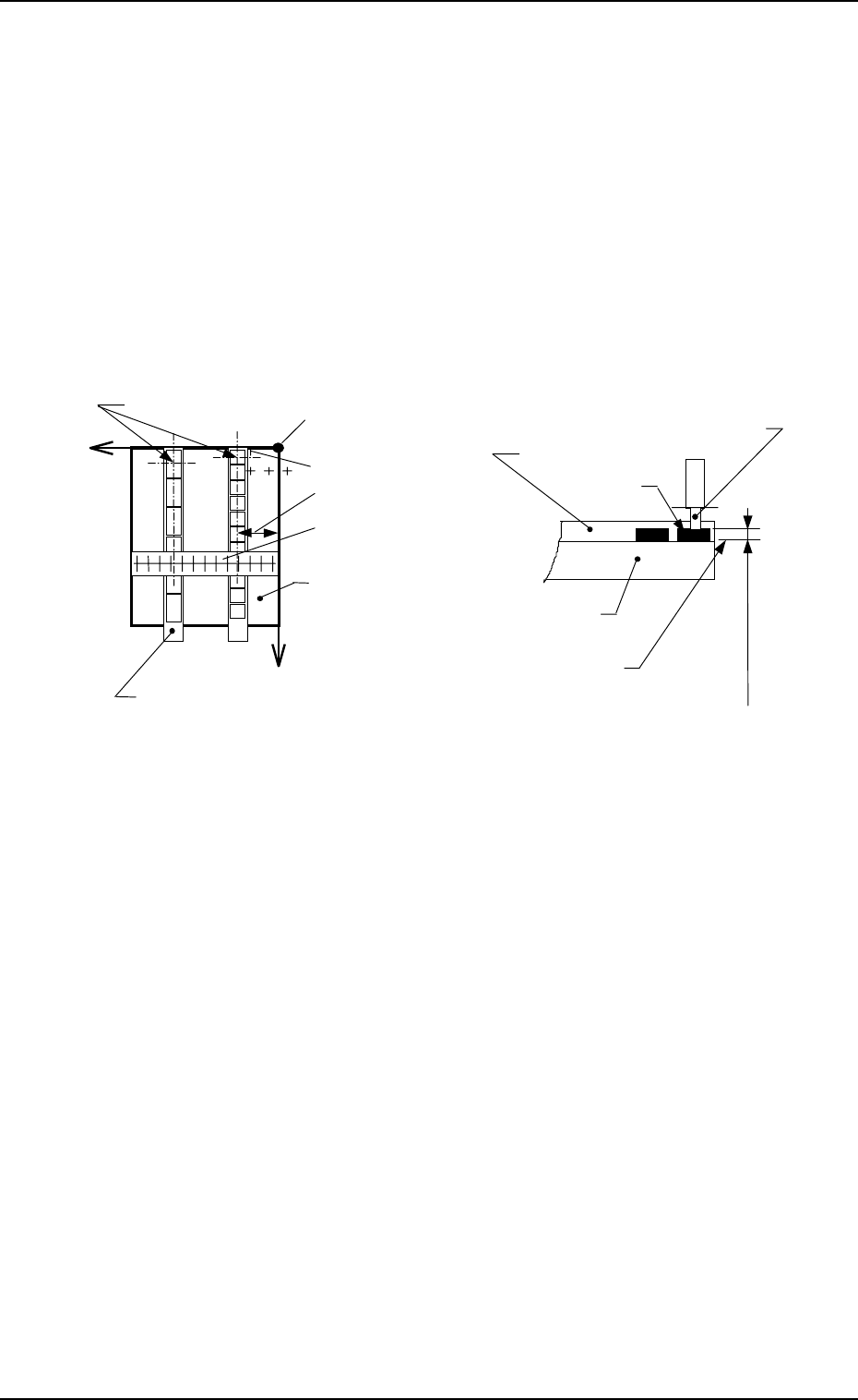
*2 OFFSET
[X (mm)] : Enter the distance in the X direction between the reference
position of the vibratory stick feeder unit and the pick-up po-
sition.
[Y (mm)] : Enter the distance between the end (pushing face) of the vibra-
tory stick feeder and the pick-up position.
Vacuum Nozzle
Carrier Stick Magazine
Carrier Stick Magazine
Component
Pick-Up Level
(Component Library)
X
+
++
+
+
++
+
Y
Pick-Up Points
Position Offset Y
Position Offset X
Reference Point of Pick-Up Level
Reference Point of Vibratory Stick Feeder Unit
Vibratory Stick
Feeder Unit
Vibratory Stick
Feeder Unit
X Direction Offset
Reading Gauge
Fig. 2.36
2.5.3 Tray Feeders (Option)
When the [DATA EDIT] key is pressed at the display for “TRAY L” (Fig.
2.33), the following display appears on the screen.
Every time the [SCREENS] key is pressed, another display appears on the
screen.
Associate component IDs by using the feeder Nos. (301 to 599) allocated to
Tray L.
Fig. 2.37-1
[SCREENS] Key
Fig. 2.37-2
2. Pattern Program
0004-002 2-44 Tg0247-PM-PM
*2
*1
2. Pattern Program
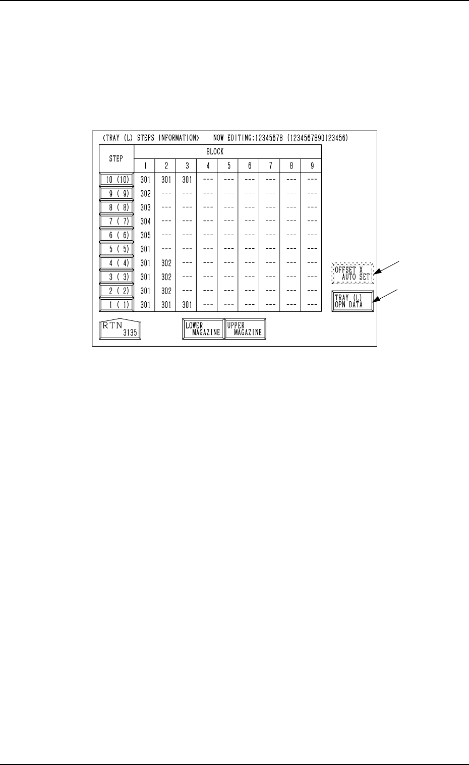
2.5.4 Tray Step Information (Option)
When the [TRAY STEP INFO] key is pressed at the display for “TRAY L”
(Fig. 2.33), the following display appears on the screen.
When the component data for Tray L is selected for editing, the tray step infor-
mation on Tray L is displayed. When the component data for Tray R is se-
lected, the information on Tray R is displayed.
Fig. 2.38
• Specify what type of components (FDR NO) you should set in which block
of which step with the tray unit.
• Up to 9 trays can be set to one step (a piece of pallet) on account of data
processing. (Max.: 9 Blocks)
Several trays can be set in the 9 blocks regardless of whether or not the same
type of components are used.
*1 [TRAY (L) OPN DATA] Key
When this key is pressed, the “TRAY (L) OPERATION DATA” display
appears on the screen, enabling the setting of a operation mode.
*2 [OFFSET X AUTO SET] Key
When this key is pressed, the “OFFSET X AUTO SETTING” display ap-
pears on the screen, enabling the selection of the [AUTO (RIGHT)] or the
[AUTO (LEFT)] key to set “R” or “L” in the text field labeled “X (mm)”
for each individual trays or all selected steps.
Note: This key may not appear, depending on how the feeder Nos. (FDR
NO) are set.
Consult our sales personnel for details.
9910-001 2-45 Tg0247-PM-PM