2OM-1064-002.pdf - 第61页
Fig. 2.40-2 Ref.: [AUTO (LEFT)] and [AUT O (RIGHT)] Keys “LEFT” or “RIGHT” represents the direction in which a tray should be pushed when it is set on the pallet. Any wasteful motion can be suppressed when T ray R is set…
9910-001 2-48 Tg0247-PM-PM
*1 [FDR] Key
Set the type of components (FDR NO) for each individual step Nos. and
blocks.
*2 OFFSET X (mm), Y (mm)
Set the coordinates of the tray origin corner to be positioned when a tray is
set in the pallet. The coordinates must be determined based on the pallet
reference position.
Note: The coordinates to be entered as positional offset are based on the
reference mark and fixed regardless of whether Tray L or R is used.
• When several trays are put on one pallet (when several blocks are used),
it is required to set positional offsets (X and Y) for each individual blocks.
By specifying the tray origin corner position, the pick-up position of
each tray is automatically calculated based on the component library data.
(“SIDE”, “PITCH”, “MATRIX”, etc.)
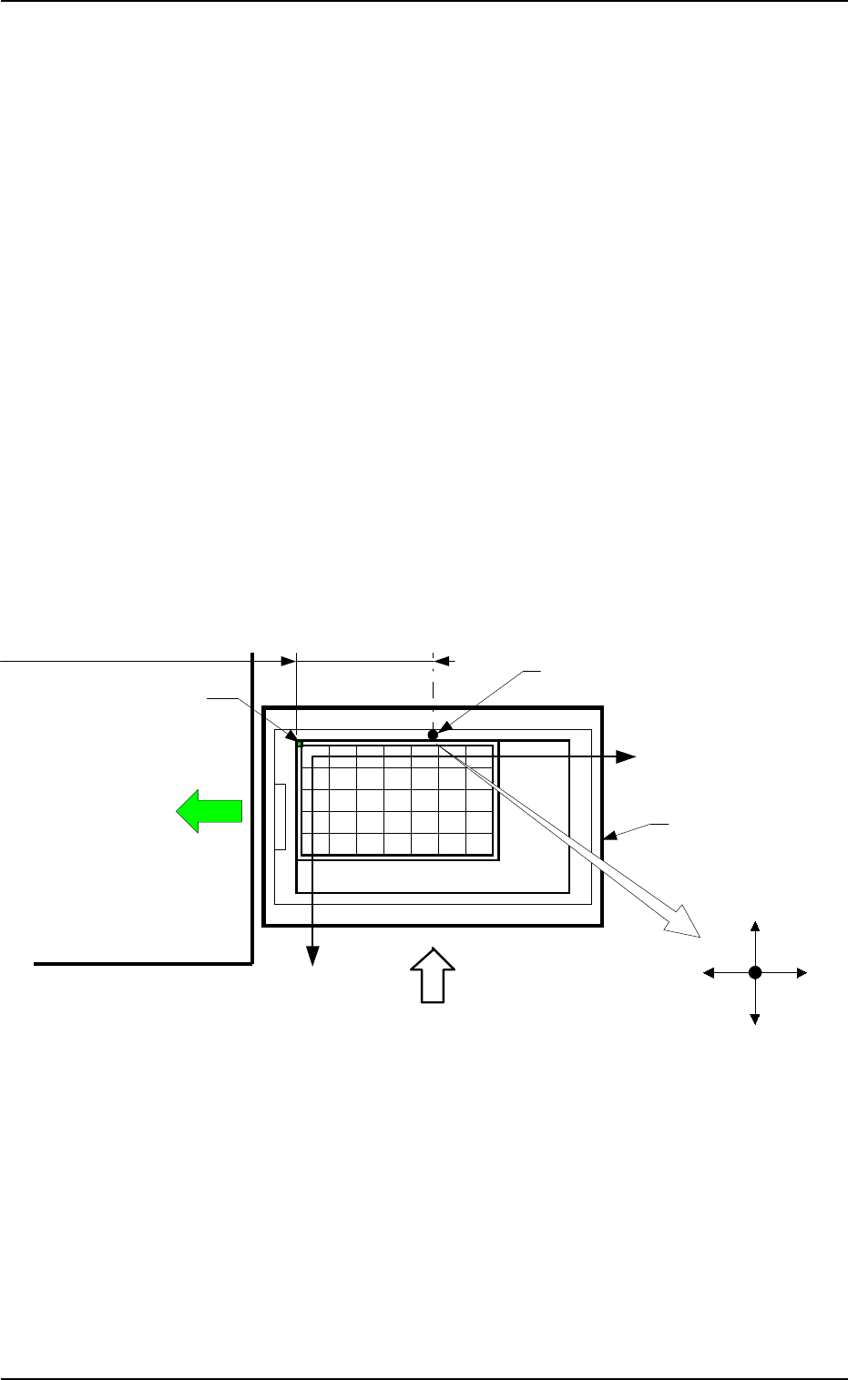
Case: Tray L
It is recommended that the tray should be set as shown in Fig. 2.40-1 to
ensure the X/Y-beam movable range as wide as possible. In this case, select
the [AUTO (LEFT)] key.
• When one tray is set on one pallet and brought to the left side, the posi-
tional offset (X, Y) is fixed as “X = -182.5 mm” and “Y = +0.0 mm”.
2. Pattern Program
Pallet Drawing Direction
Magazine
Main Body of Machine
Pallet Supply Direction
Reference Mark (Rivet)
Tray Origin Corner
Matrix Y Direction
Matrix X Direction
Positional Offset X: -182.5 mm (Fixed)
X (+)X (-)
Y (-)
Y (+)
Beam A Side
Fig. 2.40-1
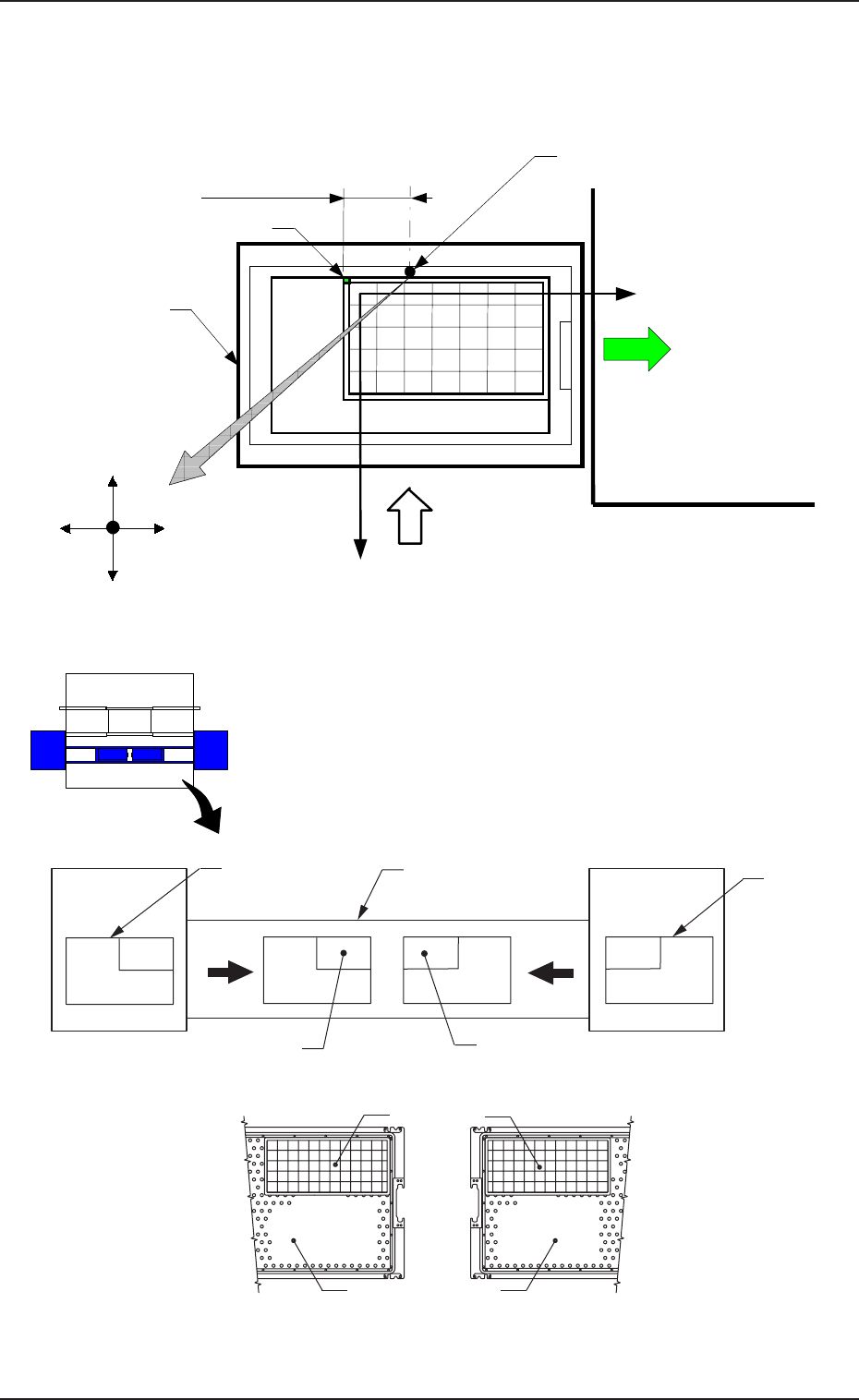
Fig. 2.40-2
Ref.: [AUTO (LEFT)] and [AUTO (RIGHT)] Keys
“LEFT” or “RIGHT” represents the direction in which a
tray should be pushed when it is set on the pallet.
Any wasteful motion can be suppressed when Tray R is
set at the upper right corner of the pallet and Tray L at the
upper left corner as shown in Fig. 2.41.
Beam B Side
Beam A Side
Tray
Tray
Pallet
Pallet
[AUTO (RIGHT)]
[AUTO (LEFT)]
Fig. 2.41
9910-001 2-49 Tg0247-PM-PM
2. Pattern Program
Case: Tray R
It is recommended that the tray should be set as shown in Fig. 2.40-2 to
ensure the X/Y-beam movable range as wide as possible. In this case, select
the [AUTO (RIGHT)] key.
Magazine
Pallet Drawing Direction
Main Body of Machine
Pallet Supply Direction
Reference Mark (Rivet)
Tray Origin Corner
Matrix Y Direction
Matrix X Direction
Positional Offset X
Beam A Side
X (+)X (-)
Y (-)
Y (+)
FP-5020L
FP-5020R
Tray Traverse
Pallet
Tray L (Upper
Left Corner)
Pallet
Tray R (Upper
Right Corner)
Beam A Side
9910-001 2-50 Tg0247-PM-PM
2. Pattern Program
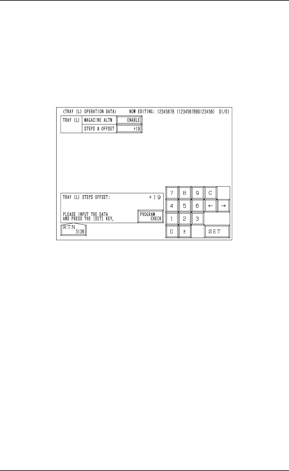
2.5.5 TRAY OPERATION DATA Display (Option)
When the [TRAY (L) OPN DATA] key is pressed at the “TRAY (L) STEPS
INFORMATION” display (Fig. 2.38), the following display appears on the
screen.
While the tray L information is being edited, the “TRAY (L) OPERATION
DATA” display appears on the screen.
While the tray R information is being edited, the “TRAY (R) OPERATION
DATA” display appears on the screen.
Fig.2.42
MAGAZINE ALTN
“ENABLE” or “DISABLE”can be set in the data box to determine whether
or not the magazine alternate function should be used.
[ENABLE] : The magazine alternate function becomes valid.
[DISABLE] : The magazine alternate function does not work.
About the magazine alternation function
When this function is used, components can be supplied during automatic
operation without stopping the machine.
STEPS # OFFSET
The steps # offset value can be entered in the data box.
Steps # Offset
This offset data is used to shift the current feeder (currently allocated com-
ponents) to the multi-layer tray feeder.
Based on the FDR No. and the component data indicated in the placement
data, the current feeder position is shifted as much as this offset.