2OM-1064-002.pdf - 第166页
FEEDER MESSAGE RA TE BAD COUNTS and # OF PICKS Set a parameter to show the slot No. of the feeder whose pick- up rate has deteriorated during automatic operation. (One of Management Information Messages) When the number …
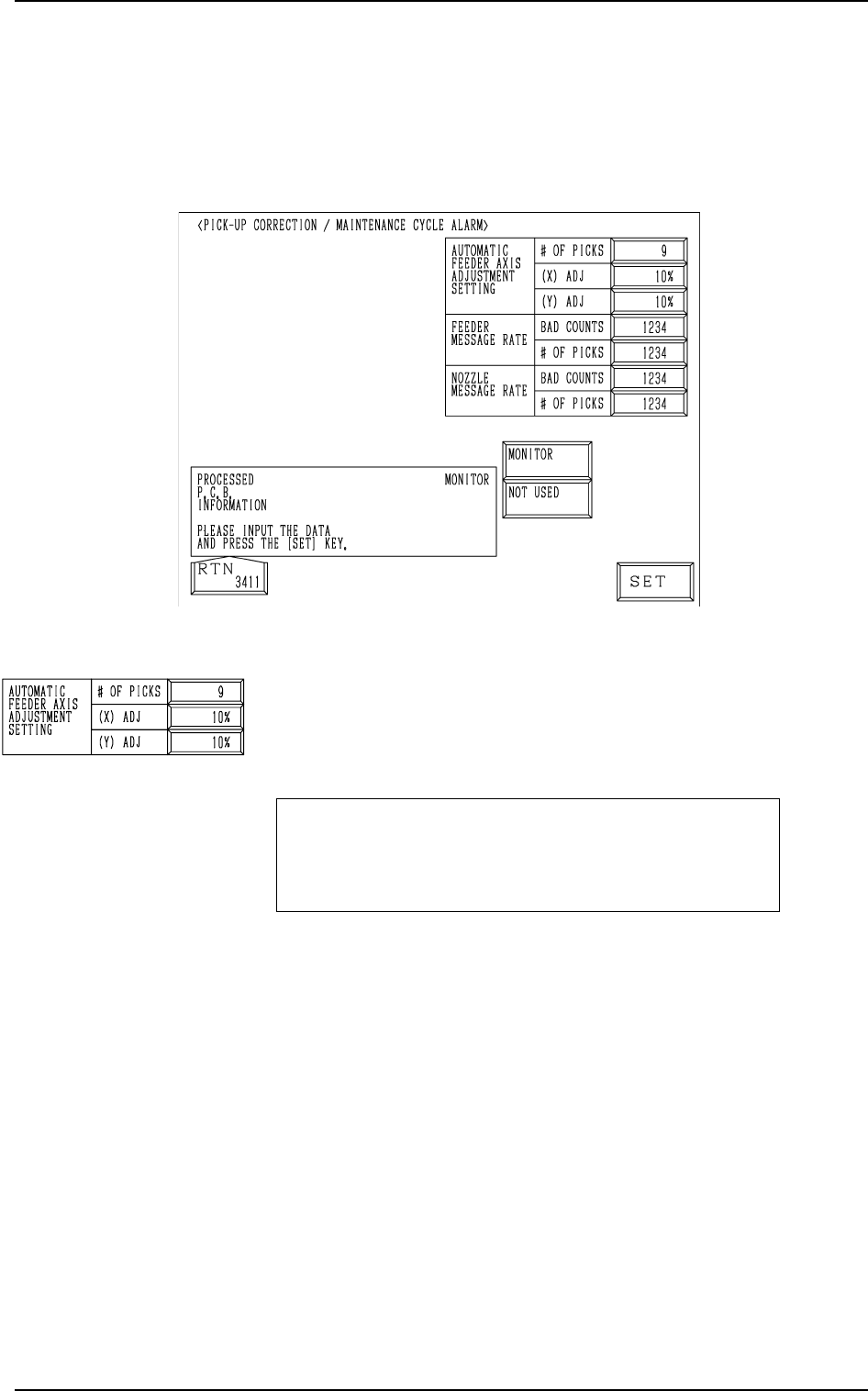
Fig. 4.2
AUTOMATIC FEEDER AXIS ADJUSTMENT SETTING
# OF PICKS, (X) ADJ, and (Y) ADJ
Set the sensitivity parameters which follow up the data learned
by using the statistical method in “FEEDER (B) OFFSET”.
New “FEEDER (B) OFFSET” = Old “FEEDER (B) OFF-
SET” + (mean of deviation
obtained n times) * Coeffi-
cient
# OF PICKS
Set the total number of collected samples when data is up-
dated or changed.
• Data Input Range: 1 to 9 (Standard Value: 3)
(X) ADJ
Set the feedback coefficient of the mean of the feeder axis’ X-
direction deviation.
• Data Input Range: 10 to 100% (Standard Value: 50%)
(Y) ADJ
Set the feedback coefficient of the mean of the feeder axis’ Y-
direction deviation.
• Data Input Range: 10 to 100% (Standard Value: 50%)
2. PICK-UP CORRECTION/MAINTENANCE CYCLE ALARM Display
2. PICK-UP CORRECTION/MAINTENANCE CYCLE
ALARM Display
When the [PU CORR/MAINT CY ALM] key is pressed at the “AUTO OP-
ERATION SET-UP” display, the following display appears on the screen.
9910-001 4-3 Tg0247-PM-PM
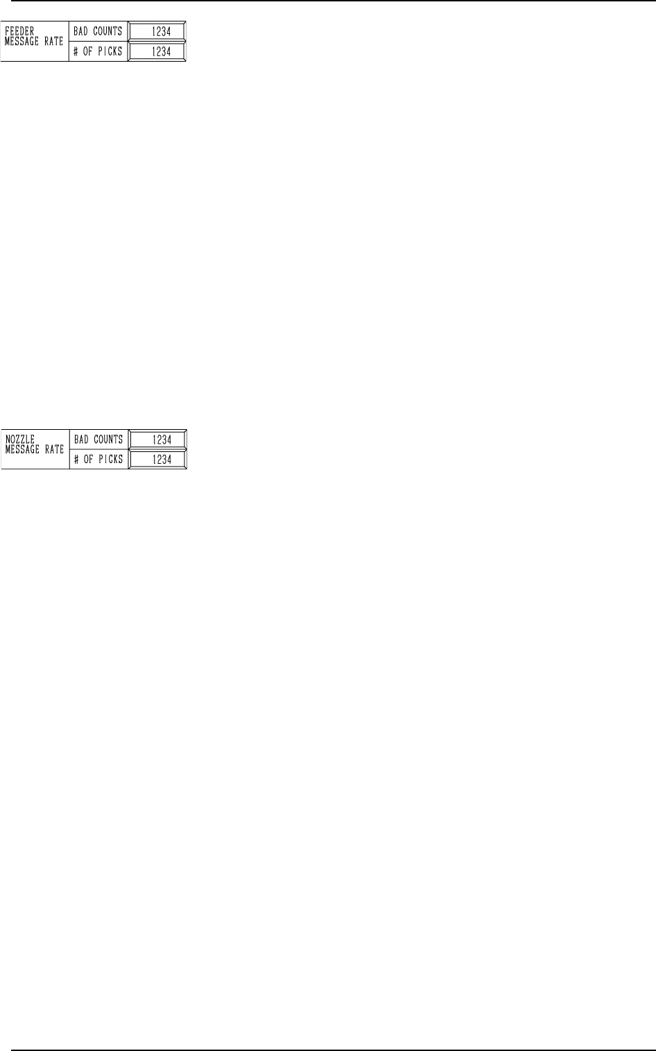
FEEDER MESSAGE RATE
BAD COUNTS and # OF PICKS
Set a parameter to show the slot No. of the feeder whose pick-
up rate has deteriorated during automatic operation. (One of
Management Information Messages)
When the number of picks has reached the set number, “BAD
COUNTS” is cleared.
When the number of pick-up errors has reached the set bad
counts before the number of picks reaches the set # of picks,
the warning message is displayed in the “MGT. INFO” box.
The number of picks and pick-up errors is managed for each
individual feeders but the data for “BAD COUNTS” and “#
OF PICKS” is equally reflected on every feeder.
• Data Input Range
BAD COUNTS : 0 to 9999
# OF PICKS : 0 to 9999
Note: When both “BAD COUNTS” and “# OF PICKS” are
set to “0”(zero) or “BAD COUNTS” is set to a num-
ber larger than “# OF PICKS”, no warning message
appears in the “MGT. INFO” box.
NOZZLE MESSAGE RATE BAD COUNTS and # OF PICKS
Set a parameter to show the nozzle No. whose pick-up rate has
deteriorated during automatic operation. (One of Management
Information Messages)
When the number of picks has reached the set number, “BAD
COUNTS” is cleared.
When the number of pick-up errors has reached the set bad
counts before the number of picks reaches the set # of picks,
the warning message is displayed in the “MGT. INFO” box.
This parameter is not reflected upon the automatic nozzle by-
pass function.
This is only for management information message.
It is recommended that a comparatively short span be set.
This function is provided to survey and avoid machine’s mal-
functions which may be caused during the start-up operation
of the machine.
• Data Input Range
BAD COUNTS : 0 to 9999
# OF PICKS : 0 to 9999
Note: When both “BAD COUNTS” and “# OF PICKS” are
set to “0”(zero) or “BAD COUNTS” is set to a num-
ber larger than “# OF PICKS”, no warning message
appears in the “MGT. INFO” box.
0004-002 4-4 Tg0247-PM-PM
2. PICK-UP CORRECTION/MAINTENANCE CYCLE ALARM Display
3. RECOGNITION ERROR IMAGE SAVE SET-UP Display
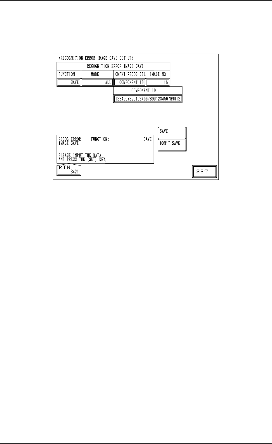
3. RECOGNITION ERROR IMAGE SAVE SET-UP Display
When the [RECOG ERR IMAGE SAVE SET-UP] key is pressed at the “AUTO
OPERATION SET-UP” display, the following display appears on the screen.
9910-001 4-5 Tg0247-PM-PM
Fig. 4.3
Set a parameter for each label (MODE, CMPNT RECOG SEL, IMAGE NO)
to analyze the cause of a recognition error in comparison with the error image
on the monitor.
When “SAVE” is set in the “FUNCTION” data box, the image which matches
the save mode (parameters set for “MODE” and “CMPNT RECOG SEL” dur-
ing operation) is stored in memory.
• Error images stored in memory can be saved on a floppy disk and sent to us
for error analysis.
Refer to “4.1 Error Image Save Function of Section 3 in Volume 4” for
details.
FUNCTION : “SAVE” or “DON’T SAVE”
MODE : “ALL”, “CMPNT RECOG”, “P.E.C. RECOG”
CMPNT RECOG SEL:
“OFF”, “CAMERA NO”, “COMPONENT ID”, “FEEDER NO”,
“HEAD NO”, or “NOZZLE NO”
CAMERA NO : The camera No. must be specified.
COMPONENT ID : The component ID must be specified.
FEEDER NO : The feeder No. must be specified.
HEAD NO : The head No. must be specified.
NOZZLE NO : The nozzle ID must be specified.
Note: As for “CMPNT RECOG SEL”, the set parameter is valid only
for those related to component recognition errors.
Setting of “RECOGNITION ERROR IMAGE SAVE” for “P.E.C.
RECOG.2 is unconditional.