2OM-1064-002.pdf - 第214页
13 . ROOM TEMPERA TURE A T LIGHTING TEACHING Display When the [ROOM TEMPERA TURE A T L TG TEACHING] key is pressed at the “OFFSET DA T A” display , the following display appears on the screen. 13. ROOM TEMPERA TURE A T L…
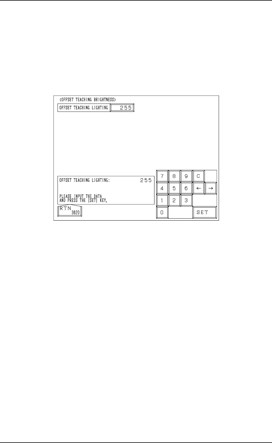
12. OFFSET TEACHING BRIGHTNESS Display
When the [OFFSET TEACHING BRIGHTNESS] key is pressed at the “OFF-
SET DATA” display, the following display appears on the screen.
Note: The values in Fig. 5.38 are determined through automatic teaching op-
eration. It is not necessary for the customer to directly enter any val-
ues.
The values differ depending upon which machine is used.
These values are used only for your reference.
12. OFFSET TEACHING BRIGHTNESS Display
Fig. 5.38
The lighting system for offset teaching is used to teach the offset data for the
component recognition camera.
The brightness values are set through automatic teaching operation based on
the image captured using the lighting system for offset teaching.
The brightness values are determined so that the best brightness is obtained for
the lighting system.
9910-001 5-43 Tg0247-PM-PM
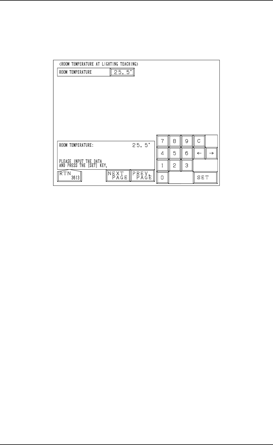
13. ROOM TEMPERATURE AT LIGHTING TEACHING
Display
When the [ROOM TEMPERATURE AT LTG TEACHING] key is pressed at
the “OFFSET DATA” display, the following display appears on the screen.
13. ROOM TEMPERATURE AT LIGHTING TEACHING Display
9910-001 5-44 Tg0247-PM-PM
Fig. 5.39
Reserved Data
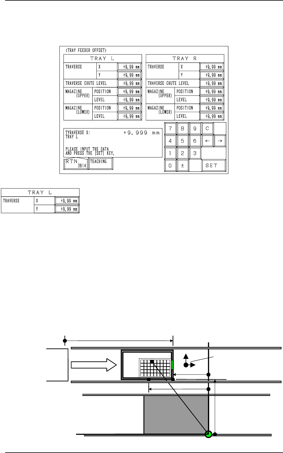
Fig. 5.40
TRAY L TRAVERSE X, Y
This offset data is used to adjust the position where a pallet is
drawn out from the magazine by the traverse shaft. The devia-
tion from the design position can be set in these data boxes.
X (Horizontal)
When a pallet is drawn out, the traverse shaft moves as far as
the specified distance where the parameter set in this data box
is added.
To increase the stroke in the pallet drawing direction, a plus
value must be entered.
Y (Vertical)
The set value is added to the travel of Beam A when compo-
nents are picked up from the tray.
As the traverse shaft is driven in one direction due to the me-
chanical structure, the adjustment of the Y direction is per-
formed using the Y axis of Beam A.
When the actual tray drawing position is located at the lower
left area (viewed from the top), compared with the design po-
sition (P.C.B. Positioning Reference: PO), plus values must be
entered in the “X” and “Y” data boxes.
14. TRAY FEEDER OFFSET Display (Option)
When the [TRAY FEEDER OFFSET] key is pressed at the “OFFSET DATA”
display, the following display appears on the screen.
14. TRAY FEEDER OFFSET Display (Option)
Fig. 5.41
TC
+576.000 mm
+325.000 mm
+535.000 mm
PO
Tray L
+755.000 mm(Design Stroke of Pallet Movement)
Y
(+)
X
(+)
Offset Signs
0004-002 5-45 Tg0247-PM-PM