2OM-1064-002.pdf - 第90页
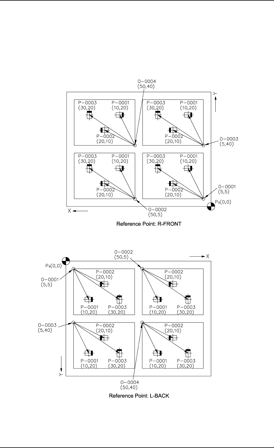
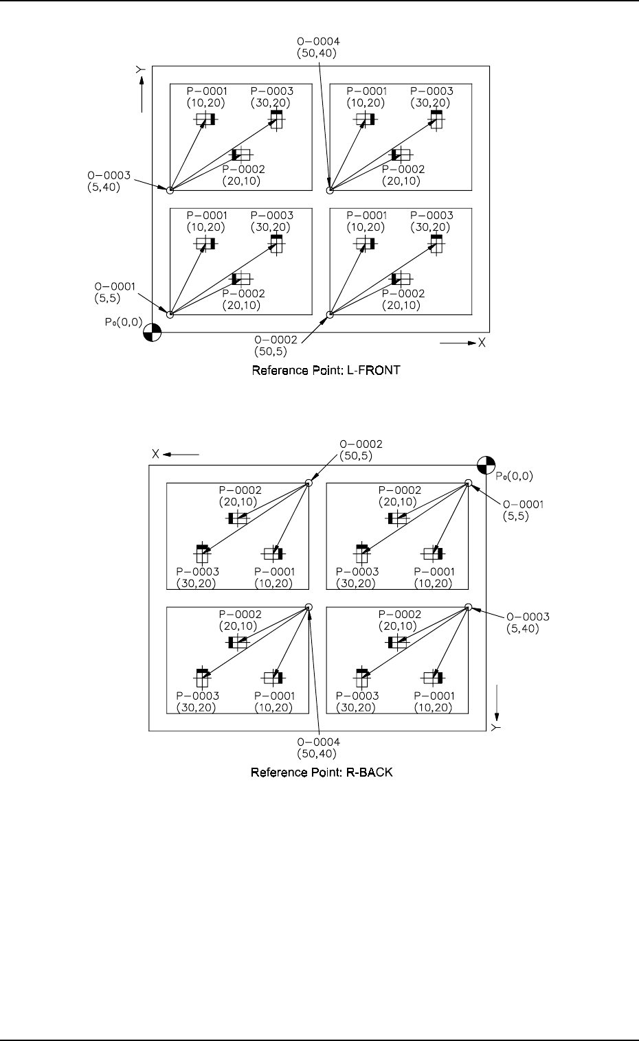
3. Example of Pattern Program Creation Fig. 2.57-4 Notes: (a) P 0 shows the P .C.B. positioning reference. (b) “O-0001”, “O-0002”, “O-0003”, and “O-0004” are called “Pat- tern Origins”. Each coordinate measured from the …
3. Example of Pattern Program Creation
3.2.3 Repetitive Placement Data
[Not to set the P.E.C. recognition function for each individual
repetitive patterns]
(1) Pattern Sample
• The figure below shows components placed on each unit P.C.B. mak-
ing the same patterns (4 patterns) repeatedly.
9910-001 2-77 Tg0247-PM-PM
Fig. 2.57-2
Fig. 2.57-1
3. Example of Pattern Program Creation
Fig. 2.57-4
Notes: (a) P
0
shows the P.C.B. positioning reference.
(b) “O-0001”, “O-0002”, “O-0003”, and “O-0004” are called “Pat-
tern Origins”. Each coordinate measured from the P.C.B. posi-
tioning reference point must be entered.
(c) Measure the coordinates (distances) based on the pattern origins
and enter them for component placement.
9910-001 2-78 Tg0247-PM-PM
Fig. 2.57-3
3. Example of Pattern Program Creation
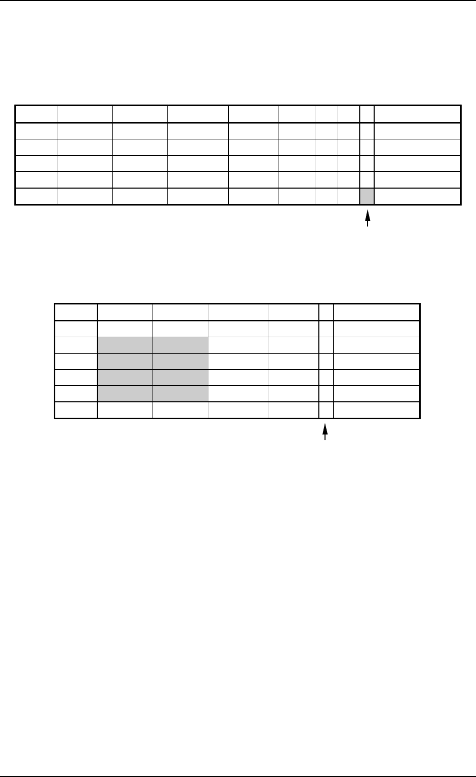
(2) Example of Data Creation
• Use placement data (P) U01 and placement data (O) U01.
• Do not enter any parameters in placement data (V) because it is not
used.
PLACEMENT DATA (P) U01
9910-001 2-79 Tg0247-PM-PM
O-NO. X(mm) Y(mm) Z(THETA) H(mm) C COMMENT
0000 +0.00 +0.00 +0
°
00’ +0.00 -
0001 +5.00 +5.00 +0
°
00’ +0.00 -
0002 +50.00 +5.00 +0
°
00’ +0.00 -
0003 +5.00 +40.00 +0
°
00’ +0.00 -
0004 +50.00 +40.00 +0
°
00’ +0.00 -
0005 +0.00 +0.00 +0
°
00’ +0.00 E
Enter “0” (zero) in all data fields of the last step and “P” or
“Q” as a control command.
Fig. 2.58
PLACEMENT DATA (O) U01
Enter “0” (zero) in all data fields of the last step and “E” as
a control command.
Fig. 2.59
P-NO. X(mm) Y(mm) Z(THETA) H(mm) FDR S V C COMMENT
0000 +0.00 +0.00 +0
°
00’ +0.00 000 - 00 -
0001 +10.00 +20.00 +0
°
00’ +0.00 101 - 00 -
0002 +20.00 +10.00 +180
°
00’ +0.00 201 - 00 -
0003 +30.00 +20.00 +90
°
00’ +0.00 301 - 00 -
0004 +0.00 +0.00 +0
°
00’ +0.00 000 - 00 P