2OM-1064-002.pdf - 第210页
9910-001 5-40 Tg0247-PM-PM 1 1 . COMPONENT RECOGNITION BRIGHTNESS Display When the [COMP . RECOG BRIGHTNESS] key is pressed at the “OFFSET DA T A” display , the following display appears on the screen. Note: The values i…
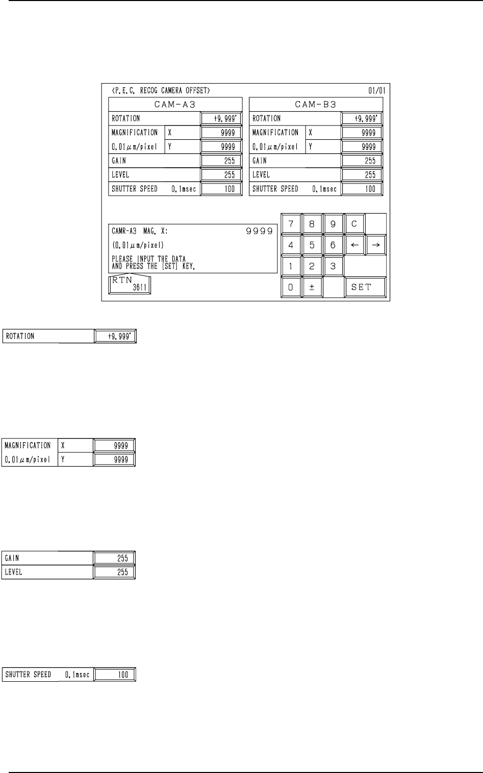
Fig. 5.36
ROTATION: Used commonly for each camera
The set parameter is used to adjust the horizontal swing of the
P.E.C. recognition camera on the X/Y beam.
Set a parameter representing the angular deviation in the scan-
ning coordinates of the camera based on the P.C.B. position-
ing X/Y coordinates (PL-XY: Origin P0).
When the camera scanning coordinates shift to P.C.B. posi-
tioning XY coordinates (PL-XY) system counterclockwise, the
sign becomes “Plus”.
MAGNIFICATION 0.01µm/pixel X (Horizontal), Y (Vertical):
Used commonly for each camera
These parameters are used to set magnification of the P.E.C.
recognition camera in the increments of 0.01 µm per pixel.
Parameters must be entered for both “X” and “Y” data boxes.
The above-mentioned offset data is automatically calculated
by using a jig P.C.B. and following the procedure described in
“P.E.C. CAMERA OFFSET & BEAM OFFSET (Step 1)”
(teaching menu).
GAIN and LEVEL: Used commonly for each camera
The set parameters are used to set the amplifications at which
the image signals of the P.E.C. recognition camera is converted
into picture information representing brightness.
This data is set as the offset value at the “CAMERA GAIN/
LEVEL” display.
Normal Fixed Value: ±0
• The smaller the gain is, the bigger the contrast becomes.
• The smaller the level is, the brighter the whole view becomes.
SHUTTER SPEED 0.1msec: Used commonly for each camera
The set parameter represents the exposure time of the camera.
Up to 180 (= 18 ms) can be set in the case of the P.E.C. recog-
nition camera.
Set parameters such that the same brightness is obtained for
“CAM-A3” and “CAM-B3”.
• The bigger the value (shutter speed data) is, the longer the
exposure time becomes, making the captured image brighter.
10. P.E.C. RECOG CAMERA OFFSET Display
When the [P.E.C. RECOG CAMERA OFFSET] key is pressed at the “OFF-
SET DATA” display, the following display appears on the screen.
10. P.E.C. RECOG CAMERA OFFSET Display
9910-001 5-39 Tg0247-PM-PM
9910-001 5-40 Tg0247-PM-PM
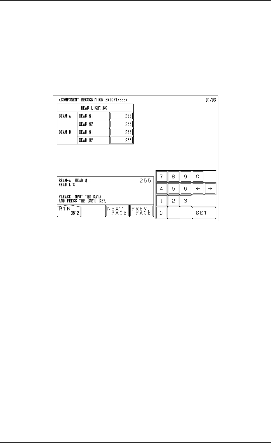
11. COMPONENT RECOGNITION BRIGHTNESS Display
When the [COMP. RECOG BRIGHTNESS] key is pressed at the “OFFSET
DATA” display, the following display appears on the screen.
Note: The values in Fig. 5.37-1 are determined through automatic teaching
operation. It is not necessary for the customer to directly enter any
values.
The values differ depending upon which machine is used.
These values are used only for your reference.
11. COMPONENT RECOGNITION BRIGHTNESS Display
Fig. 5.37-1
The head lighting devices are installed on the heads and can be moved on
Beams A and B.
These brightness values are determined such that almost the same brightness
(shades of gray) is obtained for the four head lighting devices.
The brightness values are used to adjust the brightness of the LEDs. “0” (zero)
means the darkest and “255” the brightest.
9910-001 5-41 Tg0247-PM-PM
11. COMPONENT RECOGNITION BRIGHTNESS Display
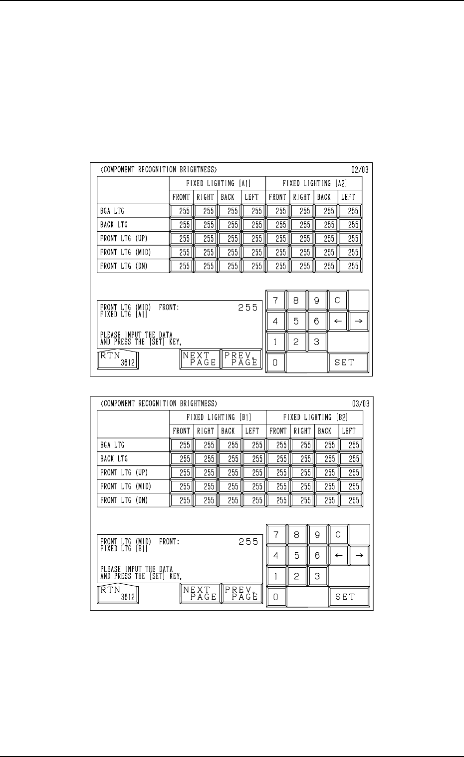
When the [NEXT PAGE] key is pressed at the “COMPONENT RECOGNI-
TION BRIGHTNESS” display (Fig. 5.37-1), the display (Fig. 5.37-2) appears
on the screen.
When the [NEXT PAGE] key is pressed at the display (Fig. 5.37-2), the dis-
play (Fig. 5.37-3) appears on the screen.
Note: The values in Figs. 5.37-2 and 5.37-3 are determined through auto-
matic teaching operation. It is not necessary for the customer to di-
rectly enter any values.
The values differ depending upon which machine is used.
These values are used only for your reference.
Fig. 5.37-3
The fixed lighting is the lighting system in which the four lighting devices are
installed on the main body of the machine. Each device has an ID name as
“A1”, “A2”, “B1”, and “B2”.
“BGA LTG”, “BACK LTG”, and “FRONT LTG (UP), (MID), (DN)” are in-
cluded in each lighting device.
The LEDs are grouped into four blocks and arranged at four corners (front,
right, rear, and left).
Fig. 5.37-2