2OM-1064-002.pdf - 第211页
9910-001 5-41 Tg0247-PM-PM 1 1. COMPONENT RECOGNITION BRIGHTNESS Display When the [NEXT P AGE] key is pressed at the “COMPONENT RECOGNI- TION BRIGHTNESS” display (Fig. 5.37-1), the display (Fig. 5.37-2) appears on the sc…
9910-001 5-40 Tg0247-PM-PM
11. COMPONENT RECOGNITION BRIGHTNESS Display
When the [COMP. RECOG BRIGHTNESS] key is pressed at the “OFFSET
DATA” display, the following display appears on the screen.
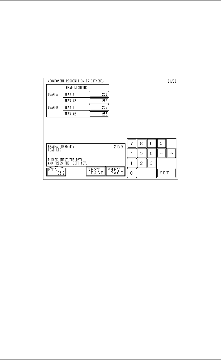
Note: The values in Fig. 5.37-1 are determined through automatic teaching
operation. It is not necessary for the customer to directly enter any
values.
The values differ depending upon which machine is used.
These values are used only for your reference.
11. COMPONENT RECOGNITION BRIGHTNESS Display
Fig. 5.37-1
The head lighting devices are installed on the heads and can be moved on
Beams A and B.
These brightness values are determined such that almost the same brightness
(shades of gray) is obtained for the four head lighting devices.
The brightness values are used to adjust the brightness of the LEDs. “0” (zero)
means the darkest and “255” the brightest.
9910-001 5-41 Tg0247-PM-PM
11. COMPONENT RECOGNITION BRIGHTNESS Display
When the [NEXT PAGE] key is pressed at the “COMPONENT RECOGNI-
TION BRIGHTNESS” display (Fig. 5.37-1), the display (Fig. 5.37-2) appears
on the screen.
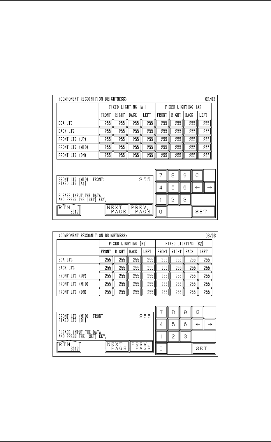
When the [NEXT PAGE] key is pressed at the display (Fig. 5.37-2), the dis-
play (Fig. 5.37-3) appears on the screen.
Note: The values in Figs. 5.37-2 and 5.37-3 are determined through auto-
matic teaching operation. It is not necessary for the customer to di-
rectly enter any values.
The values differ depending upon which machine is used.
These values are used only for your reference.
Fig. 5.37-3
The fixed lighting is the lighting system in which the four lighting devices are
installed on the main body of the machine. Each device has an ID name as
“A1”, “A2”, “B1”, and “B2”.
“BGA LTG”, “BACK LTG”, and “FRONT LTG (UP), (MID), (DN)” are in-
cluded in each lighting device.
The LEDs are grouped into four blocks and arranged at four corners (front,
right, rear, and left).
Fig. 5.37-2

• In the back lighting system, the brightness values are determined through
automatic teaching operation based on the captured image of the nozzle
diffusion plate.
The brightness is determined such that one lighting device emits lights in
good balance from 4 directions and the lights are illuminated with almost
the same brightness as that for the back lighting system of the other lighting
devices.
• The “BGA LTG” and “FRONT LTG (UP)” & “FRONT LTG (MID)” sys-
tems use a special jig to determine the brightness values through automatic
teaching operation.
The lights emitted in four directions are adjusted such that the lights re-
flected from the jig are obtained in good balance and illuminated with al-
most the same brightness as that for the BGA and front lighting (up and
middle) systems of the other lighting devices.
• The “FRONT LTG (DN)” system uses a special jig to determine the bright-
ness values through automatic teaching operation such that the lights are
illuminated with almost the same brightness as that for “FRONT LTG (DN)”
of the other lighting devices.
As the lights are emitted upward from the bottom, it is not necessary to
attain any balance.
11. COMPONENT RECOGNITION BRIGHTNESS Display
9910-001 5-42 Tg0247-PM-PM