2OM-1064-002.pdf - 第120页
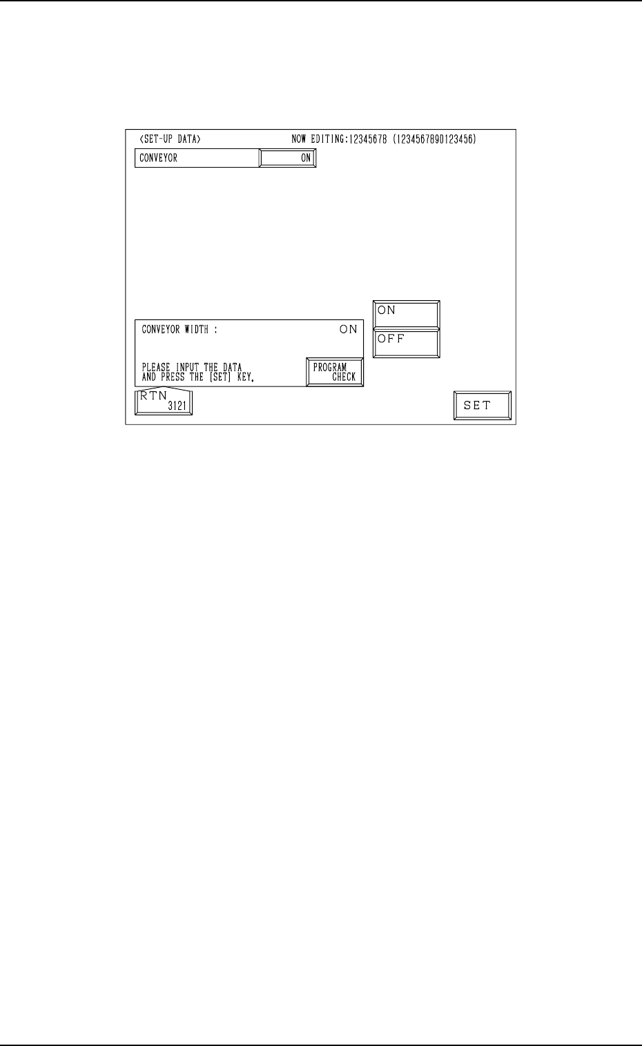
4. P A TTERN PROGRAM Display 4.4 SET-UP DA T A Display (1) When the [SET-UP DA T A] key is pressed at the “P A TTERN PROGRAM EDIT” display , the following display appears on the screen. Fig. 2.99 (2) Select the [ON] or t…
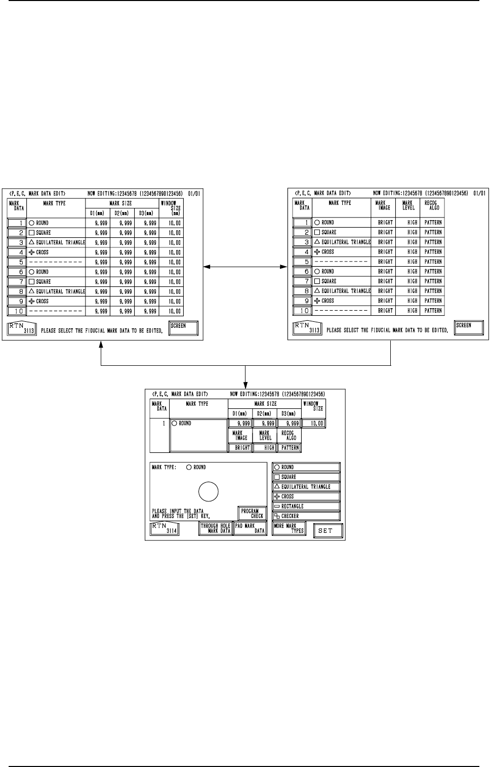
Fig. 2.97-2
Fig. 2.97-1
Fig. 2.98
[SCREEN] Key
[1]
4. PATTERN PROGRAM Display
4.3.2 P.E.C. MARK DATA EDIT Display
(1) When the [P.E.C. MARK DATA EDIT] key is pressed at the “OPERA-
TION DATA 02/03” display (Fig. 2.96-2), the display (Fig. 2.97-1) ap-
pears on the screen.
Pressing the [SCREEN] key at this display opens another “P.E.C. MARK
DATA EDIT” display.
(2) When the [1] key under the label “MARK DATA” is pressed, the display
(Fig. 2.98) appears on the screen, enabling the editing of the P.E.C. mark
data.
(3) Select the data to be edited.
(4) Enter a parameter and press the [SET] key.
(5) Press the [RTN] key. The display (Fig. 2.97-1) appears on the screen.
• When the [PROGRAM CHECK] key is pressed, the edited pattern program
is checked.
0004-002 2-107 Tg0247-PM-PM
4. PATTERN PROGRAM Display
4.4 SET-UP DATA Display
(1) When the [SET-UP DATA] key is pressed at the “PATTERN PROGRAM
EDIT” display, the following display appears on the screen.
Fig. 2.99
(2) Select the [ON] or the [OFF] key to determine whether or not the con-
veyor width should be set up automatically and press the [SET] key.
(3) Press the [RTN] key. The “PATTERN PROGRAM EDIT” display ap-
pears on the screen.
• When the [PROGRAM CHECK] key is pressed, the edited pattern program
is checked.
0004-002 2-108 Tg0247-PM-PM
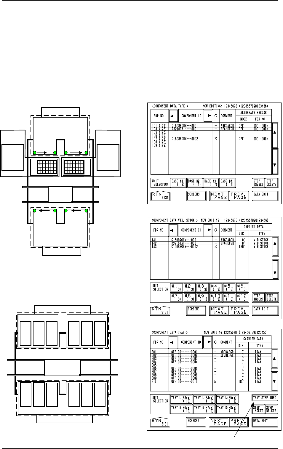
Fig. 2.102
[TAPE A]
[VIB. STICK A]
[TRAY L]
*1
701 to 799
801 to 899
FDR 101 to 139
FDR 239 to 201
Beam A
Multi-Layer
Tray Feeder L
(Option)
601 to 699301 to399
401 to499
501 to599
The numbers represent feeder Nos. (FDR NO.
)
Multi-Layer
Tray Feeder R
(Option)
Beam B
3
219
…
201
4
239
…
221
121
…
139
2
101
…
119
1
Feeder Base
Feeder Base
Feeder Base
Feeder Base
Feeder Base B
Feeder
Base A
Fig. 2.103
Fig. 2.104
Fig. 2.100
FDR 141 to 199
FDR 299
to
241
Beam B
141
149
to
Feeder Base 1
151
159
161
169
171
179
181
189
191
199
261
269
251
259
241
249
291
299
271
279
281
289
Feeder Base 2
Feeder Base 3Feeder Base 4
Beam A
For Vibratory Stick Feeders
to
to
to
to
to
to
to
to to
to
to
Feeder Base A
Feeder Base B
Fig. 2.101
For Tape Feeder
4.5 COMPONENT DATA Display
(1) When the [TAPE [A] (F101-F139)], the [VIB STICK [A] (F141-F199)],
or the [TRAY L (F301-F599)] key is pressed at the “PATTERN PRO-
GRAM EDIT” display, the corresponding display (Fig. 2.102, 2.103, or
2.104) appears on the screen.
When the [TAPE [B] (F201-F239)], the [VIB STICK B (F241-F299)], or
the [TRAY R (F601-F899)] key is pressed at the “PATTERN PROGRAM
EDIT” display, the corresponding display (similar to Fig. 2.102, 2.103, or
2.104) appears on the screen.
4. PATTERN PROGRAM Display
0004-002 2-109 Tg0247-PM-PM