2OM-1064-002.pdf - 第217页
TRA VERSE CHUTE LEVEL: Used commonly for both T rays L and R This offset data is used to adjust the level (height) of the pallet drawing chute. The deviation from the design position can be set in this data box. When a l…
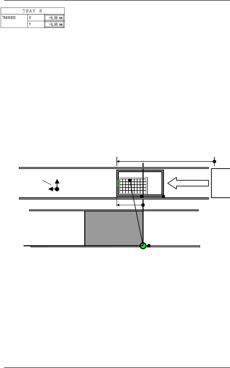
TRAY R TRAVERSE X, Y
This offset data is used to adjust the position where a pallet is
drawn out from the magazine by the traverse shaft. The devia-
tion from the design position can be set in these data boxes.
X (Horizontal)
When a pallet is drawn out, the traverse shaft moves as far as
the specified distance where the parameter set in this data box
is added.
To increase the stroke in the pallet drawing direction, a plus
value must be entered.
Y (Vertical)
The set value is added to the travel of Beam A when compo-
nents are picked up from the tray.
As the traverse shaft is driven in one direction due to the me-
chanical structure, the adjustment of the Y direction is per-
formed using the Y axis of Beam A.
When the actual tray drawing position is located at the lower right
area (viewed from the top), compared with the design position
(P.C.B. Positioning Reference: PO), plus values must be entered
in the “X” and “Y” data boxes.
14. TRAY FEEDER OFFSET Display (Option)
0004-002 5-46 Tg0247-PM-PM
Fig. 5.42
Other offset data is used for Tray R and the contents are the same
as Tray L.
PO
TC
+755.000 mm
(Design Stroke of Pallet Movement)
Tray R
Y
(+)
X
(+)
Offset Signs
+135.000 mm

TRAVERSE CHUTE LEVEL: Used commonly for both Trays
L and R
This offset data is used to adjust the level (height) of the pallet
drawing chute. The deviation from the design position can be
set in this data box.
When a level lower than the design height is set, a plus value
must be entered in the data box.
The entered plus offset value is added to the travel of the head up/
down shaft required when components are picked up from the tray.
(To increase the downward movement, a plus value must be
entered.)
MAGAZINE (UPPER) POSITION, LEVEL: Used commonly
for both Trays L and R
POSITION
This offset data is used to adjust the set-up position (magazine
connection/disconnection position) of the upper magazine. The
deviation from the design level can be set in this data box.
The entered offset value is reflected on the travel of the eleva-
tor shaft in the tray unit.
Check how the clutch is engaged when the elevator shaft is
moved to the set-up position of the upper magazine according
to the design distance (dimension) and enter an appropriate
value in the data box.
To set the elevator position in a higher level, a minus value
must be entered in the data box.
LEVEL
This offset data is used to align the traverse chute in height
with the magazine step (shelf) when a pallet is drawn from the
upper magazine. The deviation from the design level can be
set in this data box.
The entered offset value is reflected on the travel of the eleva-
tor shaft in the tray unit when the elevator is moved for the
alignment of the pallet drawing step (pallet drawing from the
upper magazine).
To set the elevator position in a higher level, a minus value
must be entered in the data box.
MAGAZINE (LOWER) POSITION, LEVEL: Used commonly
for both Trays L and R
POSITION
This offset data is used to adjust the set-up position (magazine
connection/disconnection position) of the lower magazine. The
deviation from the design level can be set in this data box. The
entered offset value is reflected on the travel of the elevator
shaft in the tray unit.
Check how the clutch is engaged when the elevator shaft is
moved to the set-up position of the lower magazine according
to the design distance (dimension) and enter an appropriate
value in the data box.
To set the elevator position in a lower level, a plus value must
be entered in the data box.
LEVEL
This offset data is used to align the traverse chute in height
with the magazine step (shelf) when a pallet is drawn from the
lower magazine. The deviation from the design level can be
set in this data box.
The entered offset value is reflected on the travel of the eleva-
tor shaft in the tray unit when the elevator is moved for the
alignment of the pallet drawing step (pallet drawing from the
lower magazine).
To set the elevator position in a lower level, a plus value must
be entered in the data box.
14. TRAY FEEDER OFFSET Display (Option)
9910-001 5-47 Tg0247-PM-PM
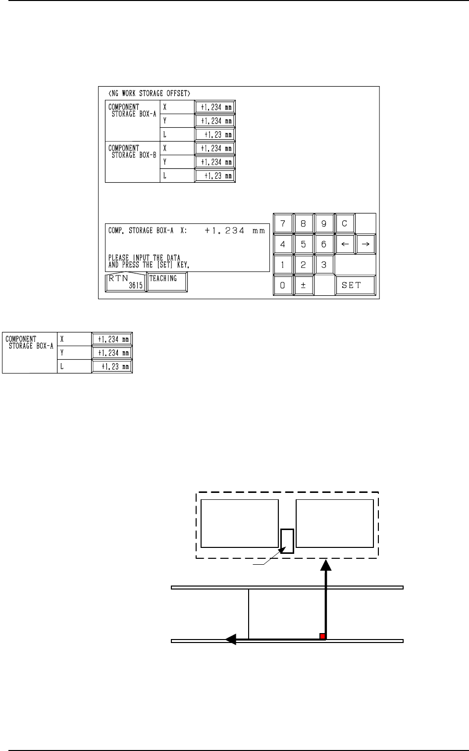
Fig. 5.43
COMPONENT STORAGE BOX-A X (Horizontal), Y (Verti-
cal), L (Height)
This offset data is used to adjust the positional (horizontal)
and vertical (height direction) deviations, compared with the
design dimensions (position) of the component storage box
located between the right and left feeder bases on the beam A
side. This offset data must be set based on the PL-XY coordi-
nate system.
The component storage box is used to store the rejected com-
ponents in the component recognition processing.
0004-002 5-48 Tg0247-PM-PM
15. NG WORK STORAGE OFFSET Display (Option)
When the [COMPONENT REJECT OFFSET] key is pressed at the “OFFSET
DATA” display, the following display appears on the screen.
15. NG WORK STORAGE OFFSET Display (Option)
PL-XY
Coordinate System
PO
Feeder Base #1
Component Storage Box A
Y
(+)
X
(+)
Feeder Base #2
Feeder Base A
Fig. 5.44
When Component Storage Box A is shifted toward the upper
left direction (viewed from the top), plus values must be en-
tered in the “X (Horizontal)” and “Y (Vertical)” data boxes.
When the level (height) of the box is set lower than the design
value, a plus value must be entered in this data box.