2OM-1064-002.pdf - 第69页
9910-001 2-57 Tg0247-PM-PM 2. Pattern Program Z=THET A (Angle) Set component placement angle data Z. • Data Input Range: 0°00´ to 359°59´ • Offset value must be entered as placement angle of fset in the data field of ste…
9910-001 2-56 Tg0247-PM-PM
2. Pattern Program
*12 [STEP COPY] Key
Pressing this key opens a display which makes it possible to copy the
selected step No. to another step.
Refer to “4.6.4 Special Operation (Step Copy) for Placement Data of Sec-
tion 2” for details.
*13 [DATA EDIT] Key
Pressing this key opens the data edit display.
Refer to “4.6.6 Editing of Placement Data of Section 2” for details.
*14 [OFFSET DATA EDIT] Key
Pressing this key opens the “PLACEMENT DATA (O) U01” display.
*15 [VISION DATA EDIT] Key
Pressing this key opens the “PLACEMENT DATA (V) U01” display.
Description of Parameters
P-NO
This shows the step Nos. of component placement data.
(The step “P-0000” always appears on the screen.)
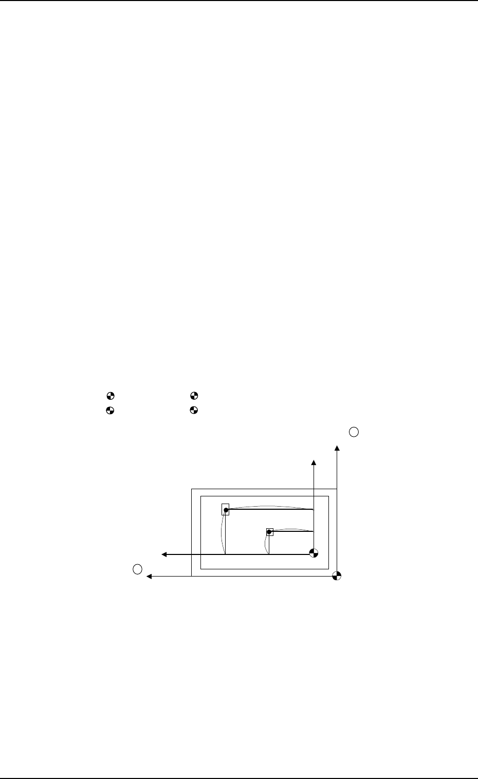
X (mm) and Y (mm)
Set component placement coordinates X and Y.
• Parameters can be entered using the absolute values (no signs) of the
distance from the placement data reference. (P-0001 to )
: The center of mark is P.C.B. positioning reference.
: The center of mark is Pattern Origin.
Y +
X +
(P.C.B.)
No (Placement Data Reference)
Po (P.C.B. Positioning Reference)
X
1
Y
1
X
2
Y
2
• Offset values in placement coordinate data must be entered in the text field
of step P-0000 labeled “X (mm)” and “Y (mm)”.
The offset values can be entered in the range of “-99.99 to +99.99 (mm)”
with + or - sign.
• Placement position can be specified by the placement coordinates data where
both pattern program offset (operation data) and X & Y parameters in step
P-0000 are added to the P.C.B. positioning reference (Po).
9910-001 2-57 Tg0247-PM-PM
2. Pattern Program
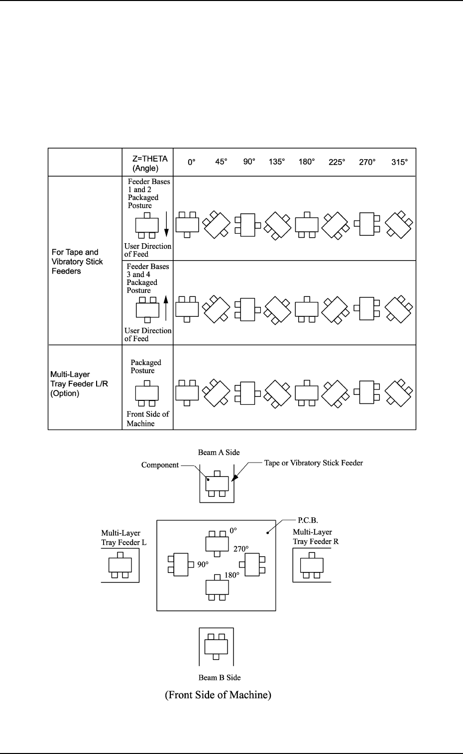
Z=THETA (Angle)
Set component placement angle data Z.
• Data Input Range: 0°00´ to 359°59´
• Offset value must be entered as placement angle offset in the data field
of step P-0000 labeled “Z=THETA”.
The offset values can be entered in the range “-99°99´ to +99°99´ ” with
+ or - sign.
Note: The following shows the placement angles changed from the pack-
aged posture of a component.
9910-001 2-58 Tg0247-PM-PM
2. Pattern Program
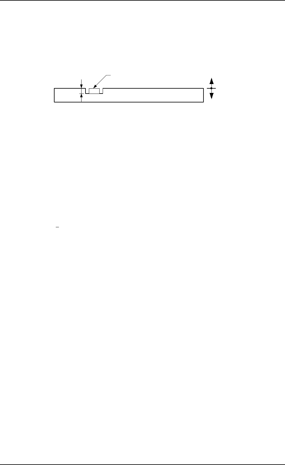
H (mm)
Set the placement height of component.
To increase the descending stroke of the head for component placement, a
plus value must be entered.
• The set parameter is used to cope with concave sections of a P.C.B. and
convex sections of a daughter P.C.B.
• The “H” data in the P-0000 step is reflected on all steps.
Reference Plane
P.C.B.
Component
+
-
FDR
Set a feeder No. (component-allocated slot No.).
• Data Input Range
101 to 109, 121 to 139, 201 to 219, 221 to 239
Note: The feeder No. set here must be specified in the component data.
• Components are picked up from the set feeder No. (slot No.).
The component No. offset is added to the feeder slot No. from which
components are actually picked up.
S
Shown is the sequence in which components are picked up.
By specifying “1” or “2” as the S data, a pair of placement steps can be
made.
: Individual Component Pick-Up/Placement
This shows that the number of cutting blocks is “1 step”.
1 : Simultaneous Pick-Up
The number of cutting blocks is “2 steps” (current and subsequent steps).
Components are recognized and placed in the order specified in the
placement data.
2 : Pick-Up Priority
The number of cutting blocks is “2 steps” (current and subsequent steps).
Components are picked up, recognized and placed in the order speci-
fied in the placement data.
Note: When the simultaneous pick-up and chuck position automatic fol-
low-up functions are used together, the chuck position automatic
follow-up function works based on the results of the component
recognition for the first step of the paired two placement steps. There-
fore, a hindrance may be caused at the other component pick-up
position. Especially, when small components are picked up simul-
taneously or components which require delicate picks are handled,
it is recommended that the pick-up priority function should be used.
• To designate the individual pick-up/placement, set “-” as the S
data.
In the following cases, “Individual Pick-Up/Placement” must be
specified because no pairing (2-step processing) can be made.
• Components whose dimension (width) exceeds 50 mm are
handled. (Component Collision due to Rotation)
• Components subjected to the divided recognition are handled.