2OM-1064-002.pdf - 第233页
1. NOZZLE STOCKER DA T A Display 9910-001 7-3 Tg0247-PM-PM *1 NOZZLE ID Set the specified nozzle IDs (nozzle IDs registered in the nozzle type data) in the “NOZZLE ID” data field for each individual nozzle stocker addres…
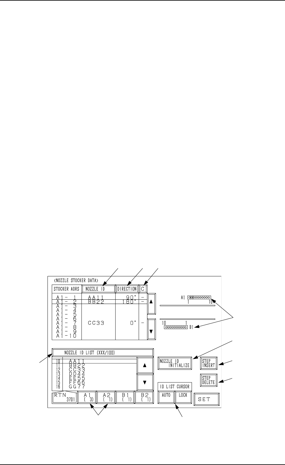
1. NOZZLE STOCKER DATA Display
At this display, nozzle types (IDs) set for the nozzle stocker section in the
machine can be registered.
The machine performs the nozzle change operation during automatic opera-
tion according to this nozzle stocker data.
The machine checks in which stocker the nozzle specified in the component
library exists and searches its address. According to the results, the machine
performs the nozzle attachment or change operation.
Nozzle Change Operation during Automatic Operation
• The nozzles attached to the heads are returned to their original nozzle stocker
addresses (addresses in which the nozzles were attached).
• When several nozzles (places) of the same type are set in the nozzle stocker
section, the machine starts to search the smallest address first and performs
the operation based on the searched address. After that, the machine pro-
ceeds to the subsequent address (next smallest address) and keeps on this
repeatedly.
• When the nozzles on both Heads #1 and #2 on the X/Y beam must be changed
simultaneously during automatic operation, the machine performs the at-
tachment operation for the new nozzles after the attached nozzles are stored
in the nozzle stocker.
• The machine automatically allocates nozzles to the heads and perform the
nozzle change operation during automatic operation. (Internal Control)
When the [PLACEMENT HEAD NOZZLE DATA] key is pressed at the “DATA
EDIT” display, the following display appears on the screen.
Fig. 7.1
*1
*2
*8
*4
*10
*7
*9
*3
*6
*5
1. NOZZLE STOCKER DATA Display
9910-001 7-2 Tg0247-PM-PM

1. NOZZLE STOCKER DATA Display
9910-001 7-3 Tg0247-PM-PM
*1 NOZZLE ID
Set the specified nozzle IDs (nozzle IDs registered in the nozzle type data)
in the “NOZZLE ID” data field for each individual nozzle stocker addresses.
Press the [NOZZLE ID INITIALIZE] key to initialize the address where no
nozzle is set. The data field is left blank.
*2 DIRECTION (Degrees): Reserved Data
In principle, “0°” must be set in the data field.
This is the reserved data for special nozzles which are used to place special
components.
*3 C
Control commands can be set.
“-” : This command handles the steps as those used for component place-
ment.
“S”: This command invalidates the steps.
This command prohibits the use of the nozzle in the stocker address where
the nozzle ID is already set.
When “S” (bypass designation) is set, the control process is handled in the
same way as the blank setting.
Color Coding for *1, *2, and *3
Green : The nozzle is used in the current pattern program.
Yellow : The nozzle is used in a pattern program other than the current
one.
White : The nozzle is not used in the pattern program registered in the
machine.
Gray : The nozzle is not registered in the component library data.
Red : The nozzle is not registered in the nozzle type data and the com-
ponent library data.
*4 [NOZZLE ID INITIALIZE] Key
When this key is pressed, the nozzle ID (nozzle stocker data) at the cursor
position is initialized.
When the [NOZZLE ID INITIALIZE] key is selected and the [SET] key is
pressed, the nozzle ID is initialized (cleared). The selected [NOZZLE ID
INITIALIZE] key turns red.
Note: When the nozzle related to the nozzle ID set at the cursor position is
attached to the pick-up head, the nozzle ID cannot be initialized
with the [NOZZLE ID INITIALIZE] key.
Bring the nozzle back to the stocker through manual operation and
initialize the nozzle ID with the [NOZZLE ID INITIALIZE] key.
*5 [STEP INSERT] Key
When this key is pressed, one line is added to the step (nozzle stocker data)
at the cursor position.
The subsequent nozzle IDs (IDs below the cursor position) are shifted down
by one line.
*6 [STEP DELETE] Key
When this key is pressed, one line of nozzle ID (nozzle stocker data) at the
cursor position is deleted.
The subsequent nozzle IDs (IDs below the cursor position) are shifted up
by one line.
1. NOZZLE STOCKER DATA Display
*7 [A1 ( X)] to [B2 ( X)] Keys
These keys are used to select a nozzle stocker.
*8 These represent nozzle stockers.
The line cursor turns blue when it is located at the nozzle stocker whose
data is being edited.
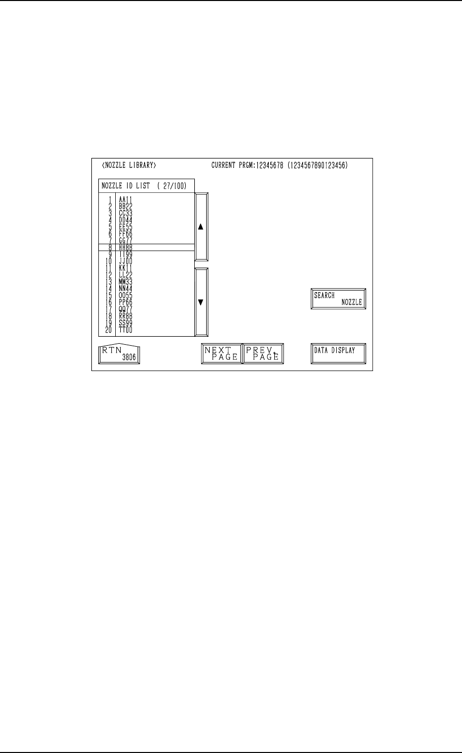
*9 [NOZZLE ID LIST (XXX/100)] Key
When the [NOZZLE ID LIST (XXX/100)] key is pressed, the display (Fig.
7.2) appears on the screen, showing the list of the registered nozzle IDs.
Fig. 7.2
• When the [SEARCH NOZZLE] key is pressed, the “SERACH NOZZLE”
display appears on the screen.
When the desired nozzle ID is entered and searched, the line cursor
moves to the found one.
Refer to “4. SEARCH NOZZLE Display of Section 8” for details.
• When the [DATA DISPLAY] key is pressed, the display (Fig. 7.3) ap-
pears on the screen, enabling the checking of the parameters set for the
specified nozzle ID.
9910-001 7-4 Tg0247-PM-PM