2OM-1064-002.pdf - 第244页
*2 *3 *1 Fig. 8.8-1 Fig. 8.8-2 [CHNG] Key *4 *4 3. NOZZLE TYPE DA T A SA VE MODE Display *1 NOZZLE ID When the data box of the label “NOZZLE ID” is pressed, a parameter can be entered in the data box. Enter a new nozzle …
2. NOZZLE TYPE DATA Display
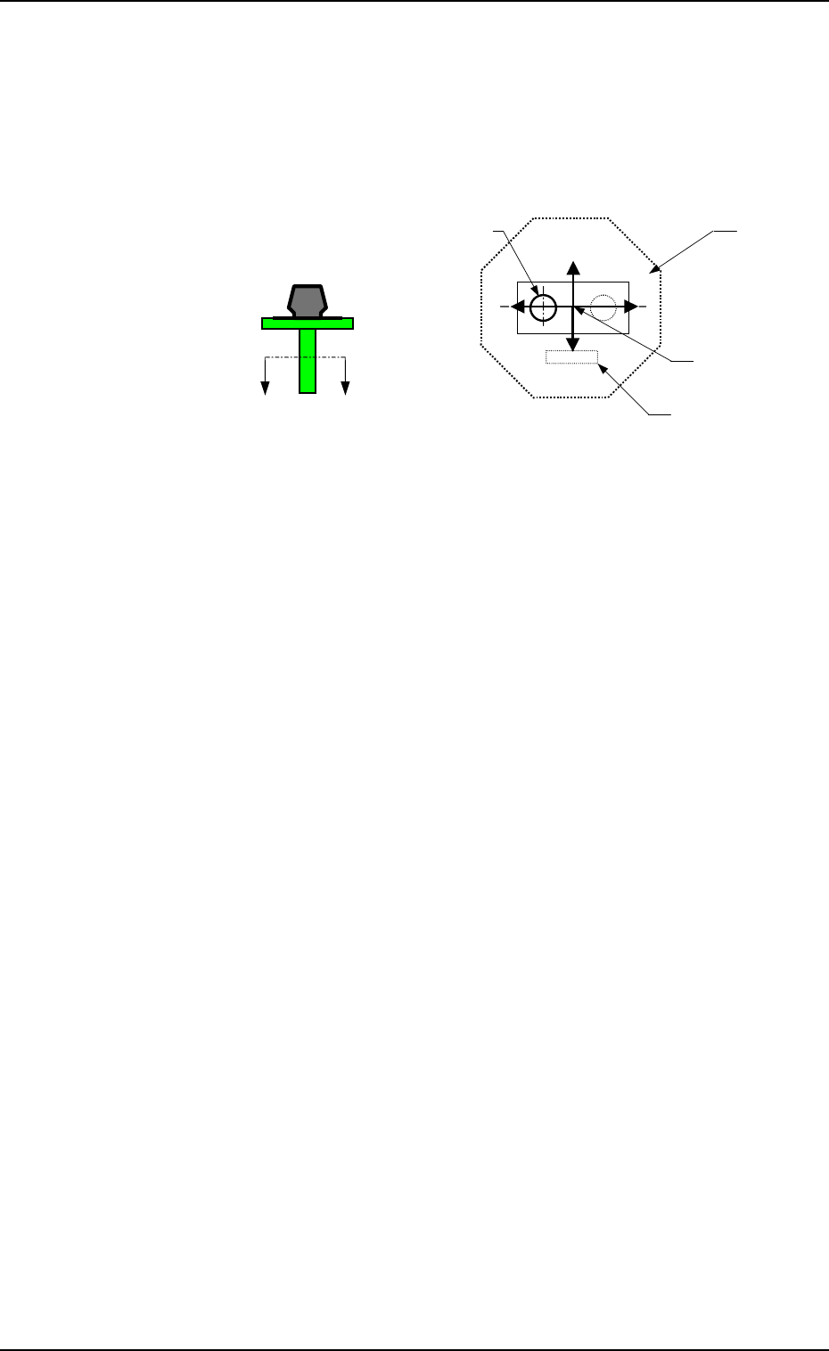
POSITION X (Horizontal), Y (Vertical)
The set parameters are used to specify the center position of
Pick-Up Hole (1) based on the nozzle center.
• Data Input Range
X: 99.99 to +99.99
Y: 99.99 to +99.99
Set X and Y as shown in Fig. 8.7.
A
’
A
Fig. 8.7 Sectional View A-A’
When no relevant hole is found, set the data values (X, Y) as
“0, 0”.
Up to 4 pieces of pick-up holes can be specified.
Operation
• Press the data key to be edited and use the ten-key pad or the
option keys to enter a parameter. Then, press the [SET] key.
• When the [RTN] key is pressed, the “NOZZLE TYPE DATA
SAVE MODE” display appears on the screen.
Note: When a special nozzle is attached, the nozzle type data
must be registered as new one.
9910-001 8-7 Tg0247-PM-PM
X(+)
Y(+)
Pick-Up Hole (1)
Nozzle Center
Diffusion Plate
Imprinted Nozzle ID
X(-)
Y(-)
*2
*3
*1
Fig. 8.8-1
Fig. 8.8-2
[CHNG] Key
*4
*4
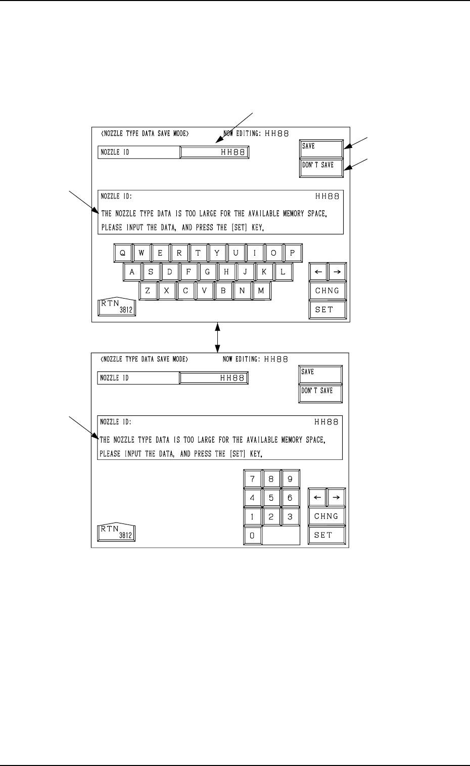
3. NOZZLE TYPE DATA SAVE MODE Display
*1 NOZZLE ID
When the data box of the label “NOZZLE ID” is pressed, a parameter can
be entered in the data box.
Enter a new nozzle ID and press the [SET] key. A new nozzle is registered
with the entered ID.
*2 [SAVE] Key
The created nozzle data is saved.
When the same nozzle ID exists, another “NOZZLE TYPE DATA SAVE
MODE” display (Fig. 8.9) appears on the screen, enabling the selection of
whether or not the nozzle data should be replaced with the existing one.
*3 [DON’T SAVE] Key
When the [DON’T SAVE] key is pressed, the edited nozzle type data is not
saved.
Note: When there is not enough memory capacity, the message is issued at
*4 and the modified data cannot be saved.
3. NOZZLE TYPE DATA SAVE MODE Display
When the [RTN] key is pressed at the “NOZZLE TYPE DATA” display (Fig.
8.2-1), the following display appears on the screen.
Every time the [CHNG] key is pressed, the display changes.
9910-001 8-8 Tg0247-PM-PM
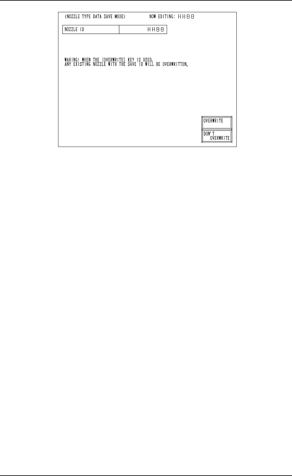
3. NOZZLE TYPE DATA SAVE MODE Display
Fig. 8.9
[OVERWRITE] Key: When this key is pressed, the nozzle type data is re-
placed with the existing one and updated.
[DON’T OVERWRITE] Key: The edited data is not saved.
Operation Procedure
(1) Select the data key *1 in Fig. 8.8-1 and enter a nozzle ID, using the ten-
key pad.
• Not to Save the Data
Press the [DON’T SAVE] key.
The data is not saved and the “NOZZLE TYPE DATA” display (Fig.
8.2-1) appears on the screen.
• To Save the Data
Proceed to Step (2).
(2) Press the [SAVE] key.
• Case: The same nozzle type data does not exist.
The nozzle type data is saved and the “NOZZLE TYPE DATA” dis-
play (Fig. 8.2-1) appears on the screen.
• Case: The same nozzle type data exists.
The “NOZZLE TYPE DATA SAVE MODE” display (Fig. 8.9) ap-
pears on the screen, enabling the selection of whether or not the exist-
ing data should be replaced with the new one.
Proceed to Step (3).
(3) Select the [OVERWRITE] or the [DON’T OVERWRITE] key at the
“NOZZLE TYPE DATA SAVE MODE” display (Fig. 8.9).
• To Replace the Existing Data with the New One
Press the [OVERWRITE] key.
The existing nozzle type data is replaced with the new one and the
“NOZZLE TYPE DATA” display (Fig. 8.2-1) appears on the screen.
• Not to Replace the Existing Data with the New One
Press the [DON’T OVERWRITE] key.
The “NOZZLE TYPE DATA SAVE MODE” display (Fig. 8.8-1) ap-
pears on the screen. Enter a nozzle ID name again with the ten-key pad.
9910-001 8-9 Tg0247-PM-PM