2OM-1064-002.pdf - 第184页
Fig. 5.14 *1 3. FEEDER (A) OFFSET and FEEDER (B) OFFSET Displays When the [FEEDER (B) OFFSET] key is pressed at the “OFF- SET DA T A” display , the following display appears on the screen. Note: The -marked function …
Note: The center of the mark is the reference point.
9910-001 5-13 Tg0247-PM-PM
3. FEEDER (A) OFFSET and FEEDER (B) OFFSET Displays
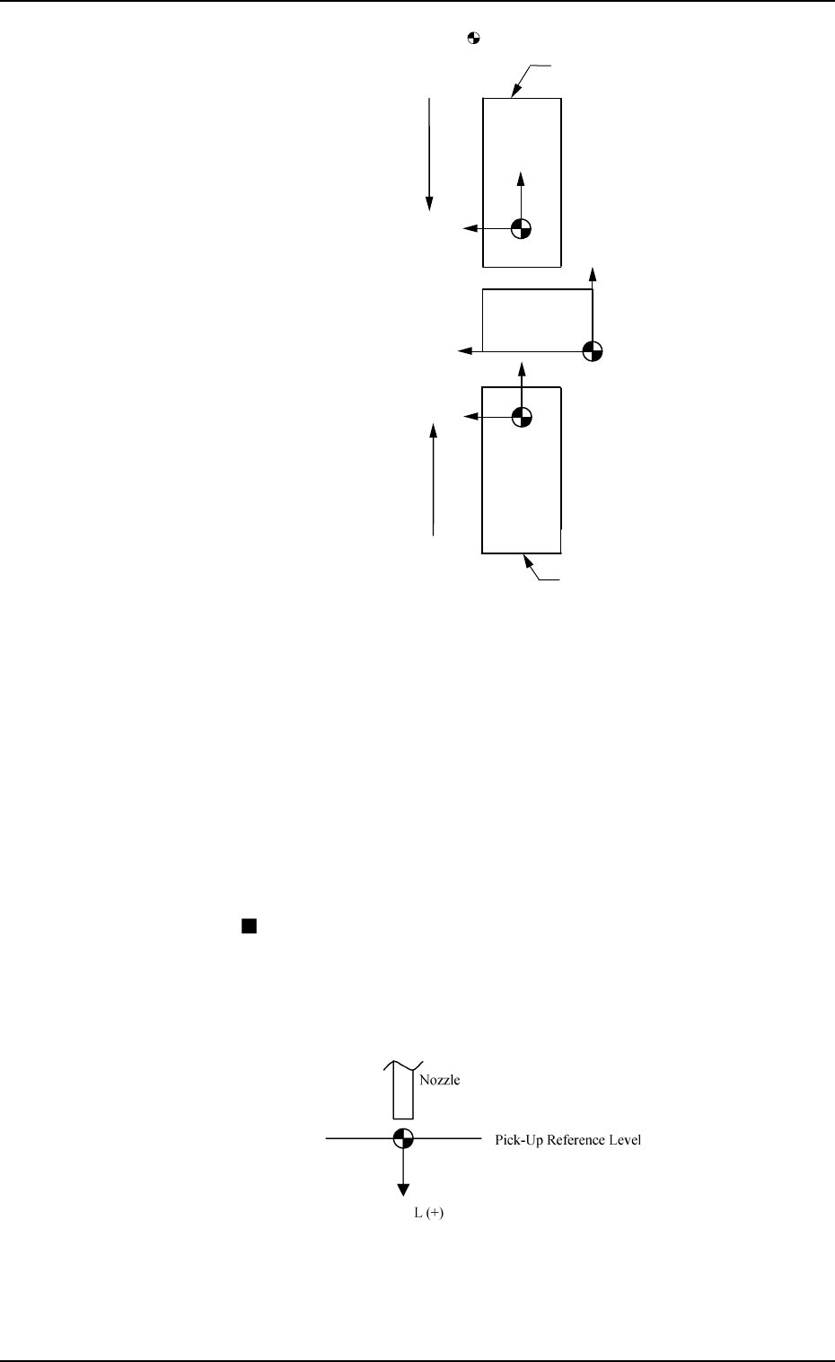
X (+)
Y (+)
P.C.B.
Rear Feeder
User Direction of Tape Feed
User Direction of Tape Feed
Front Feeder
Fig. 5.11
When offset parameters are set with a plus (+) sign, the com-
ponent pick-up directions (position) are changed to “X (+)”
and “Y (+)” shown in the above figure.
Note: Both rear (Slot Nos. 101 to 139) and front (Slot Nos.
201 to 239) feeders are not based on the feeders them-
selves. They are based on the coordinate system of the
machine.
Ref.: When the [TEACHING] key *1 is pressed, the “UNIT
MANUAL ALIGNMENT TEACH” display appears
on the screen.
Refer to “6.8.2 Feeder (A) Offset of Section 3 in Volume
4” for details.
FEEDER (A) OFFSET L (mm)
The set parameters are used to adjust the deviation of the
feeder’s component pick-up height based on the design dimen-
sions for each individual feeder slot Nos. (FDR. NO.).
These parameters are reflected on the descending stroke of the
head required to pick up a component.
Fig. 5.12
When a value is entered with a plus (+) sign, the pick-up height
is changed to “L (+)” shown in the figure above, concluding
that the descending stroke has increased.
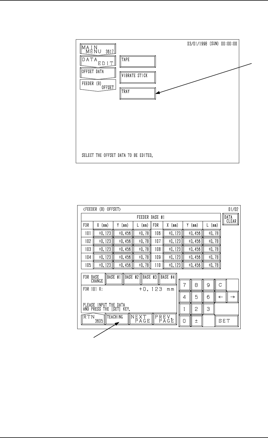
Fig. 5.14
*1
3. FEEDER (A) OFFSET and FEEDER (B) OFFSET Displays
When the [FEEDER (B) OFFSET] key is pressed at the “OFF-
SET DATA” display, the following display appears on the screen.
Note: The -marked function is optional.
9910-001 5-14 Tg0247-PM-PM
Fig. 5.13
When the [TAPE] key is selected, the following display appears
on the screen.
FEEDER (B) OFFSET X (mm) and Y (mm) (Tape Feeder)
The set parameters are used to correct the variation in each
installed feeder based on the PL-XY coordinate system (abso-
lute origin).
Enter the positional deviations from the pick-up position for
each individual feeders, including the feeder (A) offset data,
such that components can be picked up at their centers.
When the automatic feeder axis adjustment mode is enabled
for the pick-up position, this data is updated automatically as
to pick up the component center based on the results of the
component recognition for the component picked up during
automatic operation.
Refer to “5.1 AUTOMATIC FEEDER AXIS ADJUSTMENT
MODE Display of Section 3 in Volume 1” for the detailed
information on how to set the automatic feeder axis adjust-
ment mode.
Ref.: The manual alignment teaching operation is possible.
Note: The center of the mark is the reference point.
9910-001 5-15 Tg0247-PM-PM
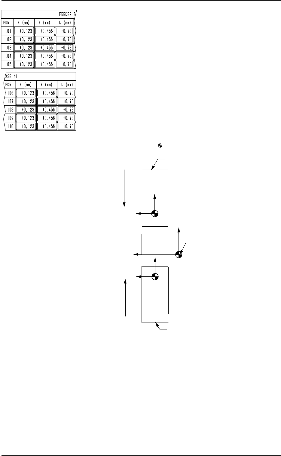
3. FEEDER (A) OFFSET and FEEDER (B) OFFSET Displays
X (+)
Y (+)
P.C.B.
Rear Feeder
User Direction of Tape Feed
User Direction of Tape Feed
Front Feeder
Absolute Origin
Fig. 5.15
When offset parameters are set with a plus (+) sign, the com-
ponent pick-up directions (position) are changed to “X (+)”
and “Y (+)” shown in the above figure.
Note: Both rear (Slot Nos. 101 to 139) and front (Slot Nos.
201 to 239) feeders are not based on the feeders them-
selves. They are based on the absolute origin.
Ref.: When the [TEACHING] key *1 is pressed, the “UNIT
MANUAL ALIGNMENT TEACH” display appears
on the screen.
Refer to “6.8.4 Feeder (B) Offset of Section 3 in Vol-
ume 4” for details.