2OM-1064-002.pdf - 第205页
A 9910-001 5-35 Tg0247-PM-PM 9. COMPONENT RECOG CAMERA OFFSET Display 9. COMPONENT RECOG CAMERA OFFSET Display When the [COMP . RECOG CAMERA OFFSET] key is pressed at the “OFF- SET DA T A” display , the following display…
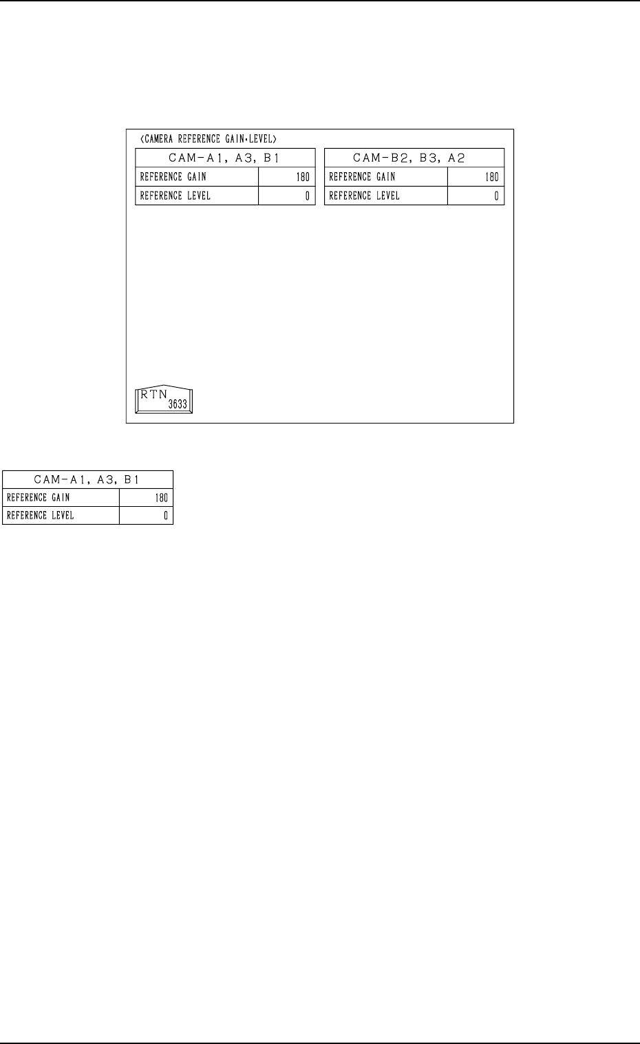
Fig. 5.32
REFERENCE GAIN/LEVEL: Used commonly for each cam-
era
All parameters are set through the automatic teaching opera-
tion.
Note: This is just an information display (editing impossible).
9910-001 5-34 Tg0247-PM-PM
8. CAMERA REFERENCE GAIN · LEVEL Display
8. CAMERA REFERENCE GAIN · LEVEL Display
When the [CAMERA REFERENCE GAIN/LEVEL] key is pressed at the “OFF-
SET DATA” display, the following display appears on the screen.
A
9910-001 5-35 Tg0247-PM-PM
9. COMPONENT RECOG CAMERA OFFSET Display
9. COMPONENT RECOG CAMERA OFFSET Display
When the [COMP. RECOG CAMERA OFFSET] key is pressed at the “OFF-
SET DATA” display, the following display appears on the screen.
Every time the [NEXT PAGE] or the [PREV. PAGE] key is pressed, the next or
the previous page appears, enabling you to set parameters for different cam-
eras.
P. C.B. Positioning
X/Y Coordinates
PL-XY
PL-Y (+)
PL-X (+)
P0
CAM-B1CAM-B2
CAM-A2
CAM-A1
(Front Side of Machine)
Top View
Com
p
onent Reco
g
nition Camera
Com
p
onent Reco
g
nition Camera
Fig. 5.33
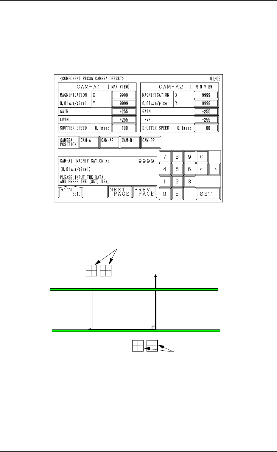
• Parameters can be entered for each individual cameras “CAM-A1”, “CAM-
A2”, “CAM-B1”, and “CAM-B2”.
Fig. 5.34
MAGNIFICATION 0.01µm/pixel X (Horizontal), Y (Vertical):
Used commonly for each camera
These parameters are used to set the magnification of the com-
ponent recognition camera in the increments of 0.01 µm per
pixel.
Parameters must be entered for both X and Y directions.
This offset data is automatically calculated through teaching
operation which is performed, using a jig component for mag-
nification measurement.
GAIN/LEVEL: Used commonly for each camera
These parameters are used to set amplifications at which the
signals of the image taken by the component recognition cam-
era is converted into the picture information representing bright-
ness.
Parameters are set as the offset values for camera reference
gain and level.
Normal Fixed Value: ±0
• The lower the gain is, the bigger the contrast becomes.
• The lower the level is, the brighter the whole view becomes.
SHUTTER SPEED 0.1msec
The set parameter represents the exposure time of the camera.
Up to 110 (= 11 ms) can be set in the case of the component
recognition camera.
Set parameters such that the same brightness is obtained for
“CAM-A1”, “CAM-A2”, “CAM-B1”, and “CAM-B2”.
• The bigger the value (shutter speed data) is, the longer the ex-
posure time becomes, making the captured image brighter.
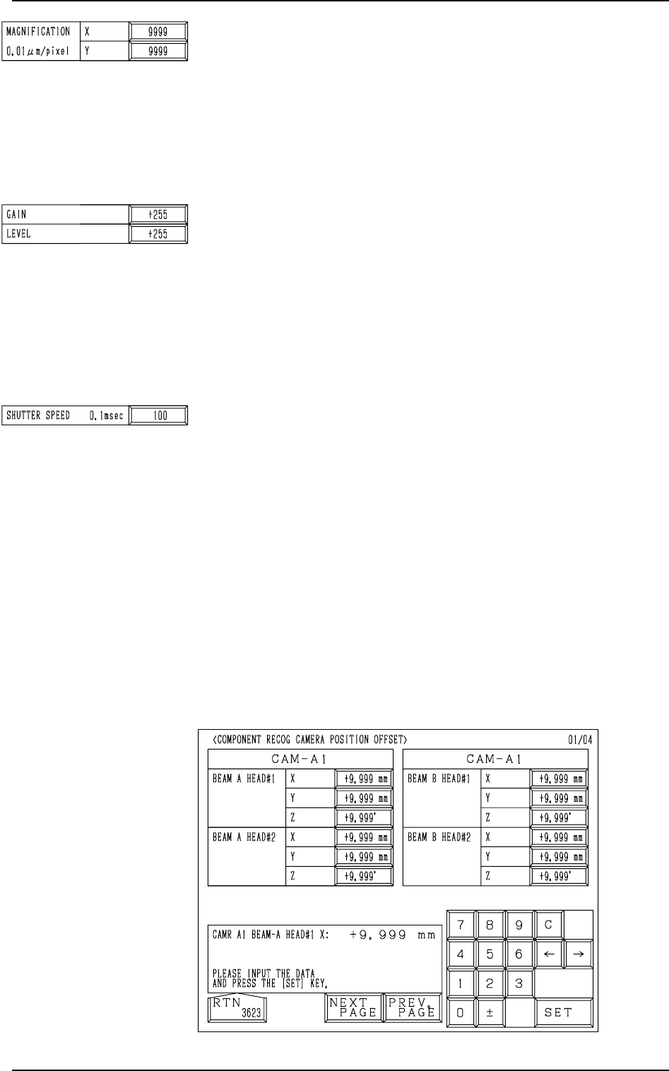
When the [CAM-A1], the [CAM-A2], the [CAM-B1], or the
[CAM-B2] key (CAMERA POSITION) is pressed at the “COM-
PONENT RECOG CAMERA OFFSET” display, the following
display appears on the screen.
Every time the [NEXT PAGE] or the [PREV. PAGE] key is
pressed, the next or the previous page appears, enabling you to
set parameters for different cameras.
9. COMPONENT RECOG CAMERA OFFSET Display
Fig. 5.35
9910-001 5-36 Tg0247-PM-PM