2OM-1064-002.pdf - 第99页
3. Example of Pattern Program Creation Placement Data (P) U03 9910-001 2-87 Tg0247-PM-PM Enter “0” (zero) in all data fields of the last step and “P” or “Q” as a control command. Fig. 2.71 Placement Data (O) U03 Enter “0…
9910-001 2-86 Tg0247-PM-PM
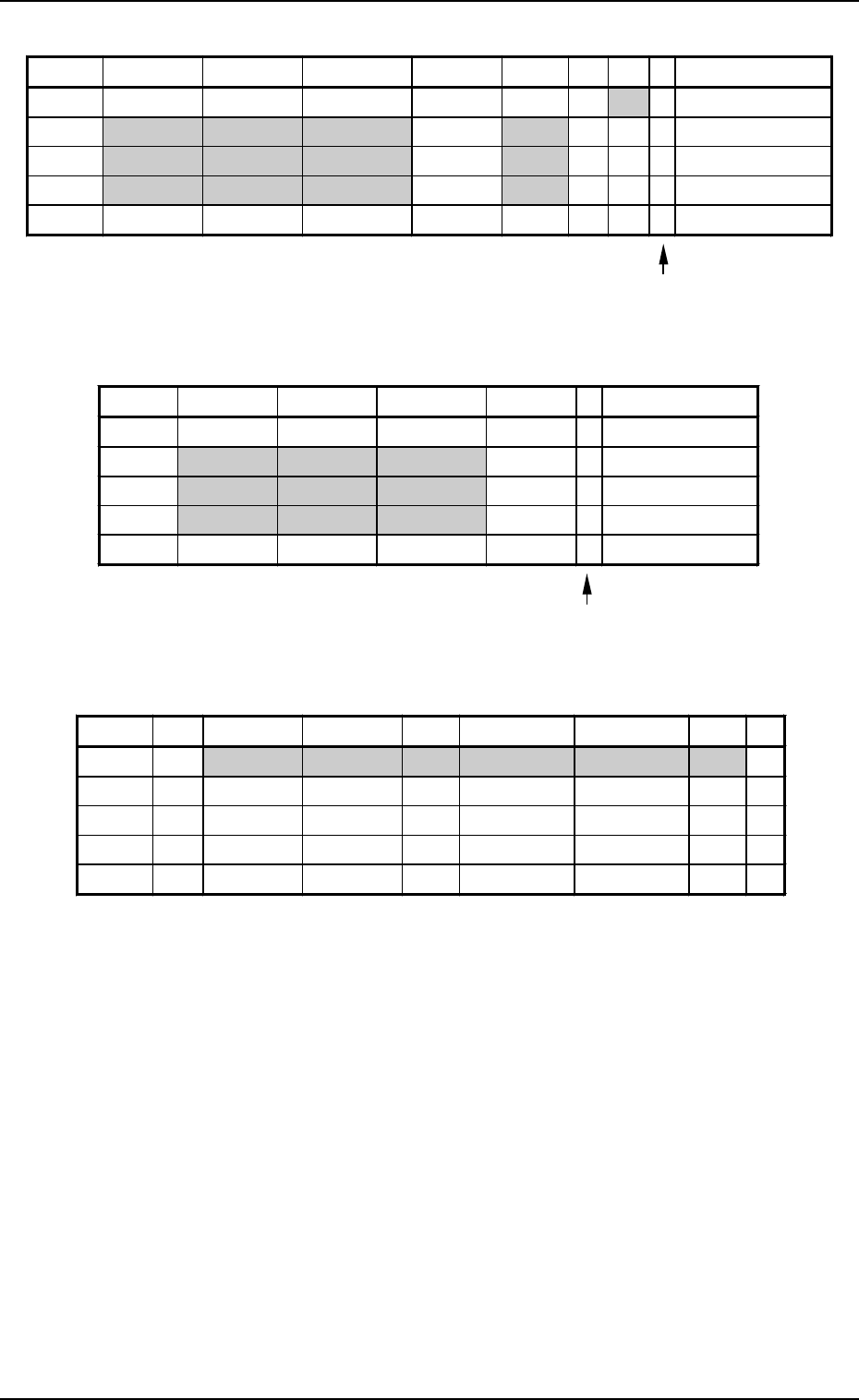
Placement Data (P) U02
3. Example of Pattern Program Creation
Enter “0” (zero) in all data fields of the last step and “P” or
“Q” as a control command.
Fig. 2.68
Placement Data (O) U02
Enter “0” (zero) in all data fields of the last step and “E” as
a control command.
Fig. 2.69
Placement Data (V) U02
Fig. 2.70
Notes: (a) The mark code Nos. registered in the “MARK DATA” data boxes
at the “OPERATION DATA” display must be entered in the “F1”
and “F2” data fields.
(b) V-0001, V-0002, V-0003 ... These Nos. correspond to the place-
ment steps.
Do not enter any parameter unless the marks at the placement
position for each individual components should be recognized.
P-NO. X(mm) Y(mm) Z(THETA) H(mm) FDR S V C COMMENT
0000 +0.00 +0.00 +0
°
00’ +0.00 000 - 02 -
0001 +20.00 +5.00 +90
°
00’ +0.00 301 - 00 -
0002 +50.00 +10.00 +270
°
00’ +0.00 401 - 00 -
0003 +70.00 +10.00 +0
°
00’ +0.00 601 - 00 -
0004 +0.00 +0.00 +0
°
00’ +0.00 000 - 00 P
O-NO. X(mm) Y(mm) Z(THETA) H(mm) C COMMENT
0000 +0.00 +0.00 +0
°
00’ +0.00 -
0001 +5.00 +40.00 +0
°
00’ +0.00 -
0002 +5.00 +55.00 +0
°
00’ +0.00 -
0003 +5.00 +70.00 +0
°
00’ +0.00 -
0004 +0.00 +0.00 +0
°
00’ +0.00 E
V-NO. V X1(mm) Y1(mm) F1 X1(mm) Y1(mm) F2 C
0000 02 +5.00 +10.00 02 +85.00 +10.00 02 -
0001 00 +0.00 +0.00 00 +0.00 +0.00 00 -
0002 00 +0.00 +0.00 00 +0.00 +0.00 00 -
0003 00 +0.00 +0.00 00 +0.00 +0.00 00 -
0004 00 +0.00 +0.00 00 +0.00 +0.00 00 P
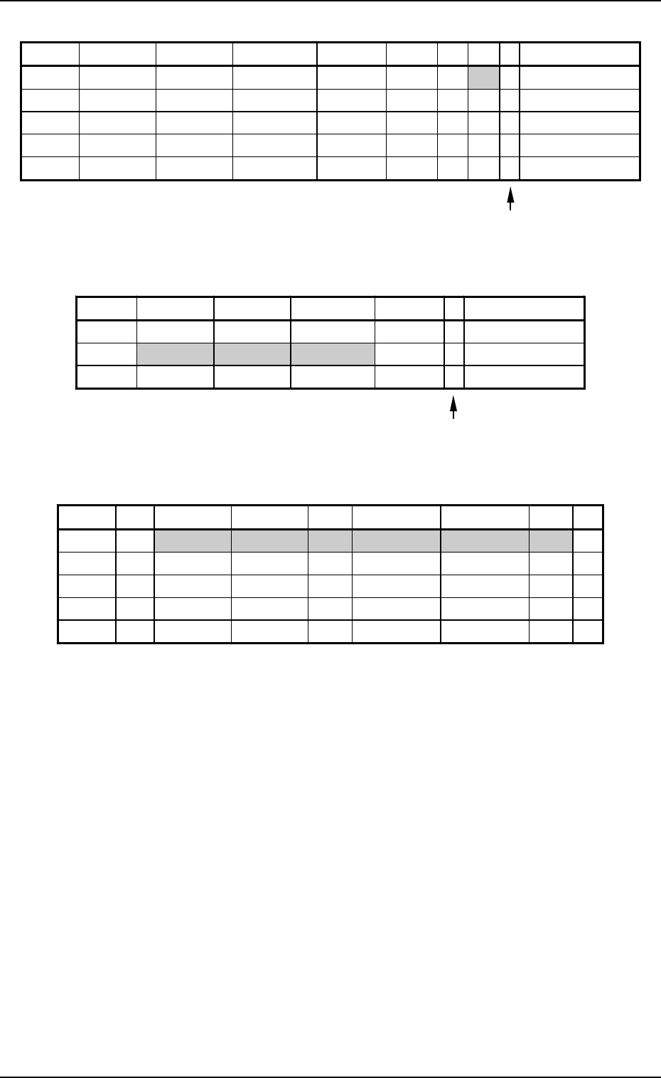
3. Example of Pattern Program Creation
Placement Data (P) U03
9910-001 2-87 Tg0247-PM-PM
Enter “0” (zero) in all data fields of the last step and “P” or
“Q” as a control command.
Fig. 2.71
Placement Data (O) U03
Enter “0” (zero) in all data fields of the last step and “E” as
a control command.
Fig. 2.72
Placement Data (V) U03
Fig. 2.73
Notes: (a) The mark code Nos. registered in the “MARK DATA” data boxes
at the “OPERATION DATA” display must be entered in the “F1”
and “F2” data fields.
(b) V-0001, V-0002, V-0003 ... These Nos. correspond to the place-
ment steps.
Do not enter any parameter unless the marks at the placement
position for each individual components should be recognized.
P-NO. X(mm) Y(mm) Z(THETA) H(mm) FDR S V C COMMENT
0000 +0.00 +0.00 +0
°
00’ +0.00 000 - 02 -
0001 +10.00 +15.00 +0
°
00’ +0.00 111 - 00 -
0002 +10.00 +40.00 +180
°
00’ +0.00 302 - 00 -
0003 +10.00 +60.00 +270
°
00’ +0.00 602 - 00 -
0004 +0.00 +0.00 +0
°
00’ +0.00 000 - 00 P
O-NO. X(mm) Y(mm) Z(THETA) H(mm) C COMMENT
0000 +0.00 +0.00 +0
°
00’ +0.00 -
0001 +65.00 +5.00 +0
°
00’ +0.00 -
0002 +0.00 +0.00 +0
°
00’ +0.00 E
V-NO. V X1(mm) Y1(mm) F1 X1(mm) Y1(mm) F2 C
0000 02 +5.00 +5.00 03 +15.00 +75.00 03 -
0001 00 +0.00 +0.00 00 +0.00 +0.00 00 -
0002 00 +0.00 +0.00 00 +0.00 +0.00 00 -
0003 00 +0.00 +0.00 00 +0.00 +0.00 00 -
0004 00 +0.00 +0.00 00 +0.00 +0.00 00 P
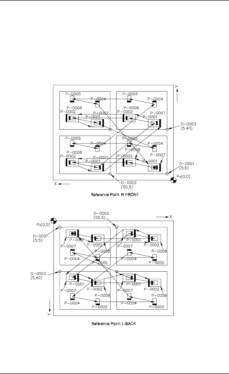
3. Example of Pattern Program Creation
3.2.6 Placement Data for Priority Sorting Function
This function is used to intentionally perform dual placement on the same
points of the unit P.C.B.’s (repetitive patterns) to shorten the time to complete
a P.C.B. by decreasing the number of the nozzle change operations required
according to the type of components or to place shield cases after internal
components are placed.
• Placement steps are grouped into some blocks and component placement
sequence can be specified for each group.
(1) Pattern Sample (Single Repetitive Pattern)
9910-001 2-88 Tg0247-PM-PM
Fig. 2.74-2
Fig. 2.74-1