2OM-1064-002.pdf - 第65页
2. Pattern Program 9910-001 2-53 Tg0247-PM-PM 2.6 Placement Data 2.6.1 Construction of Placement Data Up to 99 placement data (U01 to U99) can be set in one pattern program data, making it possible to produce unit P .C.B…
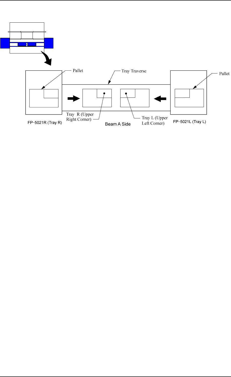
[AUTO (LEFT)] and [AUTO (RIGHT)] Keys:
“LEFT” or “RIGHT” represents the direction in which a tray
should be pushed when it is set on the pallet.
Any wasteful motion can be suppressed when Tray R is set at
the upper right corner of the pallet and Tray L at the upper left
corner as shown in Fig. 2.44.
Beam B Side
Beam A Side
9910-001 2-52 Tg0247-PM-PM
2. Pattern Program
Fig. 2.44
2. Pattern Program
9910-001 2-53 Tg0247-PM-PM
2.6 Placement Data
2.6.1 Construction of Placement Data
Up to 99 placement data (U01 to U99) can be set in one pattern program data,
making it possible to produce unit P.C.B.’s on one multi-unit P.C.B. which has
different patterns.
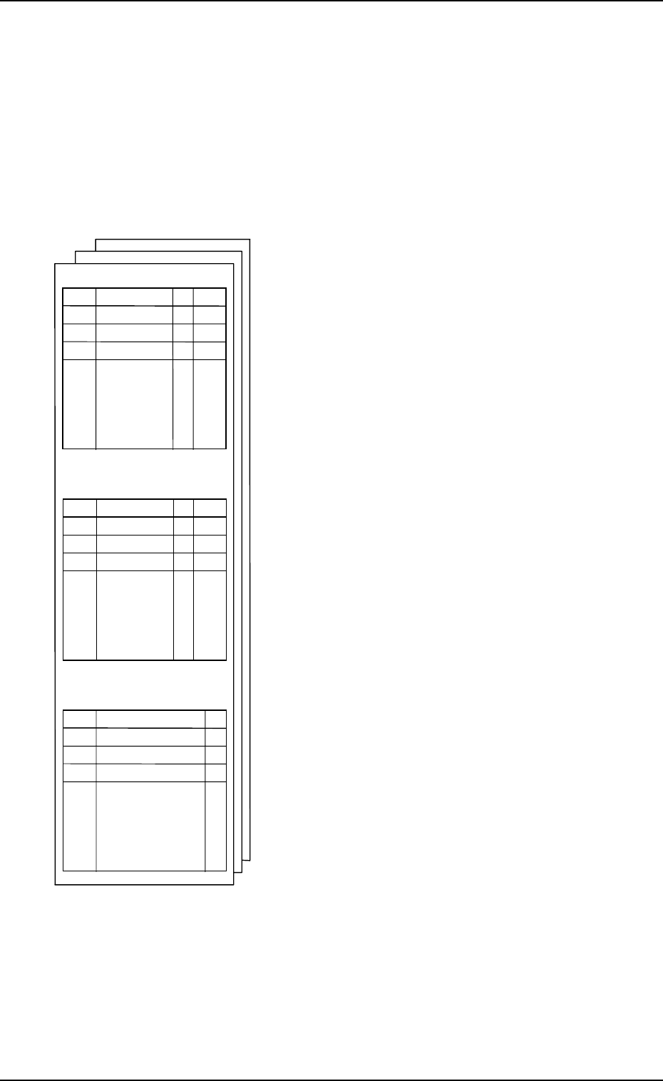
One placement data consists of three kinds of placement data - “Placement
Data (P)”, “Placement Data (O)”, and “Placement Data (V)”.
•
Placement Data (P): Component Placement Data
This placement data consists of component place-
ment coordinates X and Y, placement angle Z,
placement height H, feeder No. (FDR.), sequenc
e
data S, vision code V, control command C, an
d
comment and one step is allocated to one compo-
nent data. Data must be entered to specify place-
ment coordinates.
•
Placement Data (O): Repetitive Placement Data
When a multi-unit P.C.B. (repetitive patterns) is
used, this data is used to specify the location o
f
each unit P.C.B. on the basic multi-unit P.C.B.,
excluding the first unit.
The machine finishes multi-unit P.C.B.’s in con-
secutive order using the placement data (P) an
d
adding the positional offset shown in the offset
data (O).
(X, Y, Z, and C data is used.)
The data is also used to specify the polar coordi-
nate conversion function.
•
Placement Data (V): Vision Data for Each
Repetitive Pattern
This data is used to specify vision coordinates X1
& Y1 and the recognition mark code F1 of the first
fiducial and vision coordinates X2 & Y2 and th
e
recognition mark code F2 of the second fiducial
when specified by the vision code (V) designate
d
as “02” (2-point recognition).
P-NO
X Y Z H
C
COMMENT
0
・
・
・
・
XXX
1
2
O-NO
V X1 Y1 F1 X2 Y2 F2
C
COMMENT
0
・
・
・
・
XXX
1
2
V-NO
X Y Z H Z FDR S V
C
0
1
2
・
・
・
・
XXX
PLACEMENT DATA (P) U01
PLACEMENT DATA (O) U01
PLACEMENT DATA (V) U01
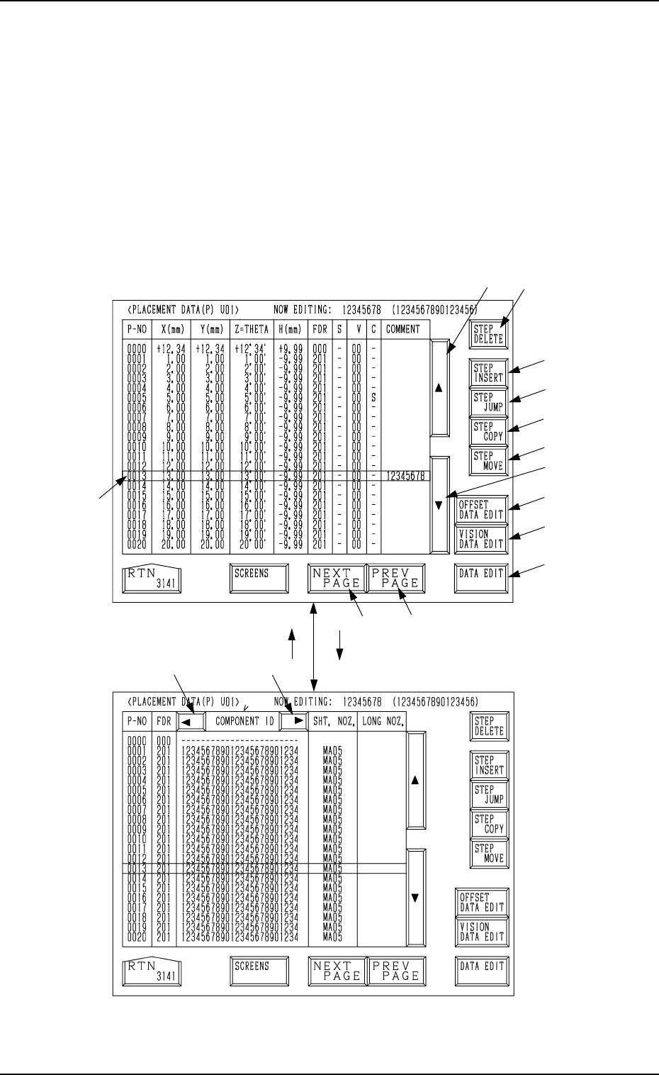
2.6.2 PLACEMENT DATA (P) Display [Component Placement Data]
When the [PLACEMENT DATA U01] key is pressed at the “PATTERN PRO-
GRAM EDIT” display, the following display appears on the screen.
Pressing the [SCREENS] key at this display opens another “PLACEMENT
DATA (P) U01” display.
A list of component placement data is displayed.
Parameters can be edited at the display opened by pressing the [DATA EDIT]
key *13.
The “PLACEMENT DATA (P) U02” display looks almost the same.
*2
*8
*9
*10
*11
*12
*3
*14
*15
*13
*5
*4
*1
[SCREENS] Key
Fig. 2.45-1
Fig. 2.45-2
*7*6
2. Pattern Program
9910-001 2-54 Tg0247-PM-PM