2OM-1064-002.pdf - 第42页
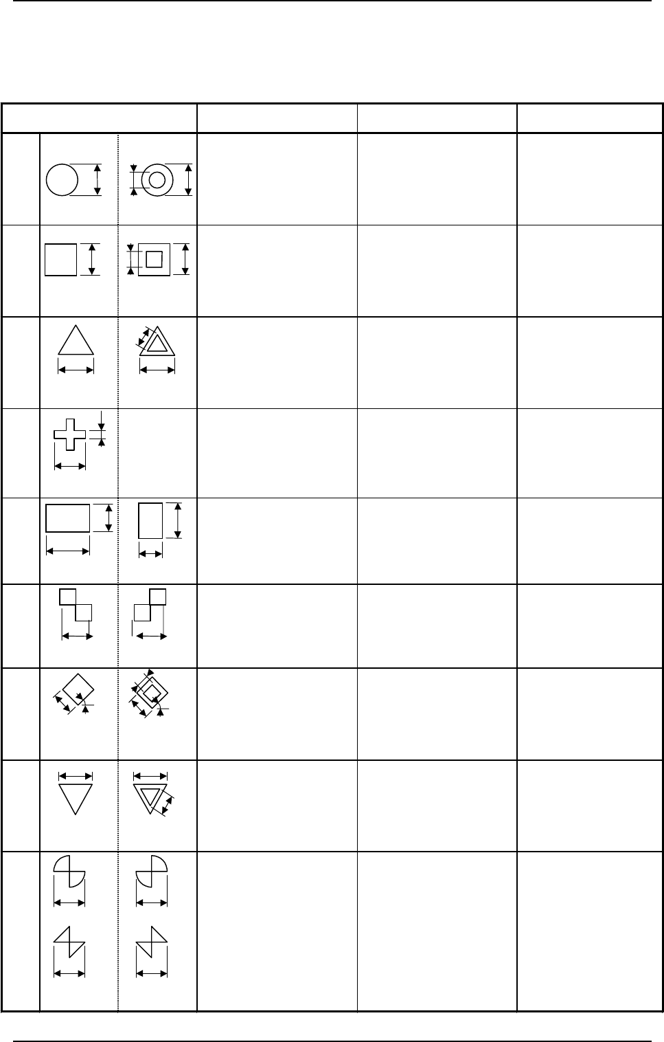
T able 2.1- 2 2. Pattern Program M ark Typ e D1 D2 Re ma rks Ch e ck e r (r ect a ngle) 0.5 to 2.0 m m ( ± 10%) 0. 5 to 2.0 m m ( ± 10%) z Mark Re fe re n ce : C ont a c t of T wo R ect a ngles T hr ough H ole ( ro un d …
2.3.4 P.E.C. Fiducial Marks
(1) Type and Size
Table 2.
1-1
Mark Type D1 D2 Remarks
Round
0.5 to 2.0 mm (±10%) 0 to 1.8 mm (±10%)
(D1 - 0.2 ≥ D2)
z
Mark Reference:
Center
z
D2:
Size of a punched
hole
Square
0.5 to 2.0 mm (±10%) 0 to 1.8 mm (±10%)
(D1 - 0.2 ≥ D2)
z
Mark Reference:
Center of Gravity
z
D2:
Size of a punched
hole
Equilateral
Triangle
(upturned)
0.5 to 2.0 mm (±10%) 0 to 1.8 mm (±10%)
(D1 - 0.2 ≥ D2)
z
Mark Reference:
Center of Gravity
z
D2:
Size of a punched
hole
Cross
0.5 to 2.0 mm (±10%) 0.2 to 1.0 mm (±10%)
(D1 / 2 ≥ D2)
z
Mark Reference:
Center of Gravity
Rectangle
0.5 to 2.0 mm (±10%) 0.5 to 2.0 mm (±10%)
z
Mark Reference:
Center of Gravity
Checker
(square)
0.5 to 2.0 mm (±10%)
z
Mark Reference:
Contact of Two
Squares
Diamond
(rotated square)
0.5 to 2.0 mm (±10%) 0 to 1.8 mm (±10%)
(D1 - 0.2 ≥ D2)
z
Mark Reference:
Center of Gravity
z
D2:
Size of a punched
hole
Equilateral
Triangle
(downturned)
0.5 to 2.0 mm (±10%) 0 to 1.8 mm (±10%)
(D1 - 0.2 ≥ D2)
z
Mark Reference:
Center of Gravity
z
D2:
Size of a punched
hole
Bow Tie
0.5 to 2.0 mm (±10%)
z
Mark Reference:
Contact of Two
Fan Shapes or
Triangles
D2
D1
D1
D1
D2
D1
(Front Side of
Machine)
(Front Side of
Machine)
D2
D1
(Front Side of
Machine
)
(Front Side of
Machine
)
(Front Side of
Machine
)
D1
D2
D2
D1
(Front Side of
Machine
)
(Front Side of
Machine
)
D1
D1
(Front Side of
Machine
)
(Front Side of
Machine
)
D1
D2
D1
(Front Side of
Machine)
(Front Side of
Machine)
Or
D1
D1
D1
Or
D1
(Front Side of
Machine
)
(Front Side of
Machine
)
45
°
D1
D1
D2
45
°
(Front Side of
Machine)
(Front Side of
Machine)
D2
D1
D1
2. Pattern Program
9910-001 2-29 Tg0247-PM-PM
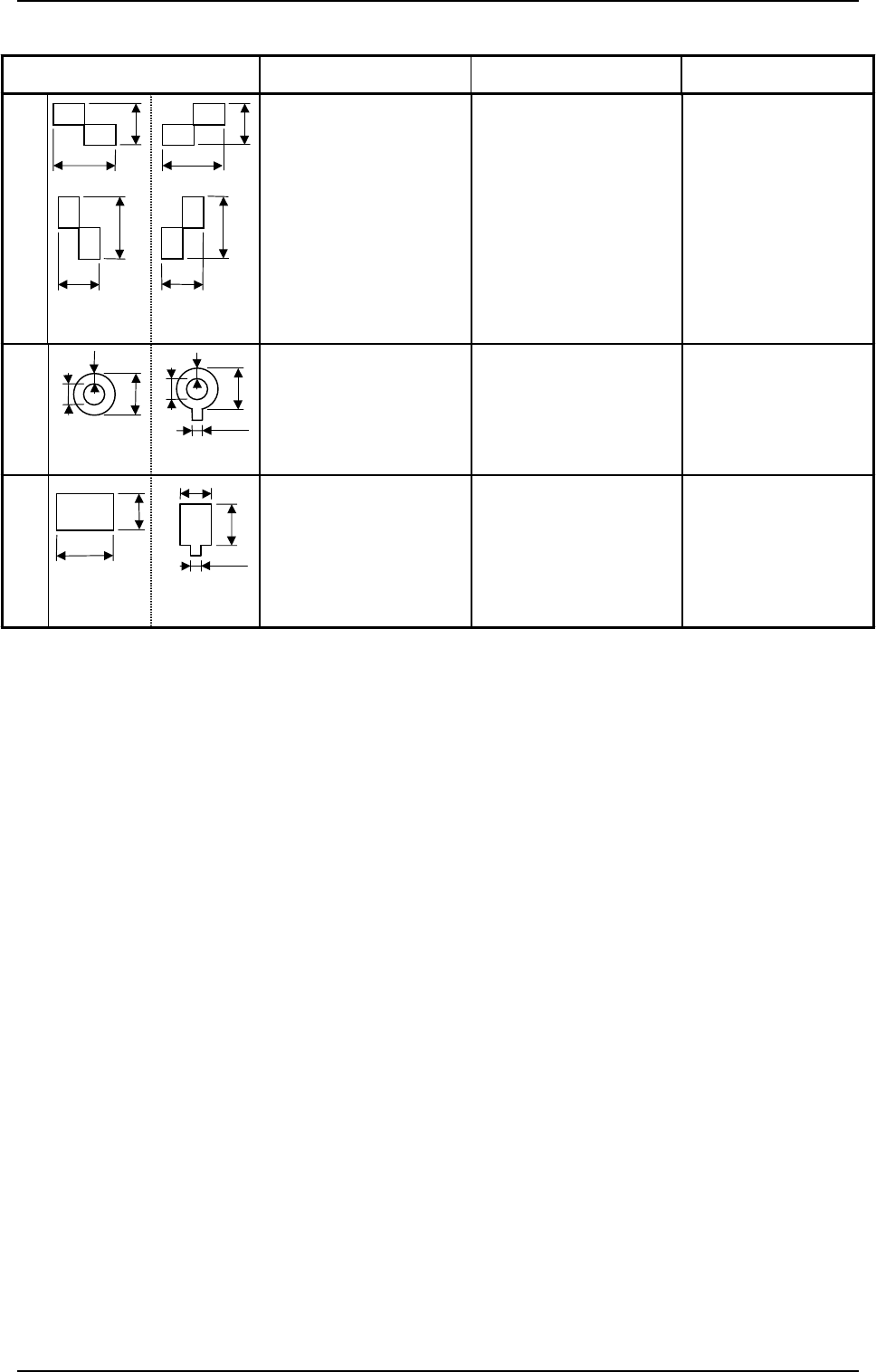
Table 2.1-2
2. Pattern Program
Mark Type D1 D2 Remarks
Checker
(rectangle)
0.5 to 2.0 mm (±10%) 0.5 to 2.0 mm (±10%)
z
Mark Reference:
Contact of Two
Rectangles
Through Hole
(
round
)
1.0 to 2.0 mm 0.5 to 1.5 mm
z
Mark Reference:
Center
z
D2: Size of a
punched hole
z
W: Min. 0.25 mm
Pad Mark
(rectangle)
0.5 to 2.0 mm 0.5 to 2.0 mm
z
Mark Reference:
Center of Gravity
D1
D2
OR
D1
D2
(Front Side of
Machine)
D1
D2
OR
D1
D2
(Front Side of
Machine)
Note a
D2
D1
(Front Side of
Machine)
D2
D1
(Front Side of
Machine)
D2
D1
W
(Front Side of
Machine)
D2
W
D1
(Front Side of
Machine)
Note a
9910-001 2-30 Tg0247-PM-PM
Range between Lines
and Tangential Lines
1/3 of Shorter Side
0.5 to 2.0
0.5 to 2.0
0.5 to 2.0
0.5 to 2.0
1/3 of Shorter Side
Range between Lines
and Tangential Lines
0.5 to 1.5
1.0 to 2.0
Min. 0.25
80° (Range
between Lines
and Tangential
Lines)
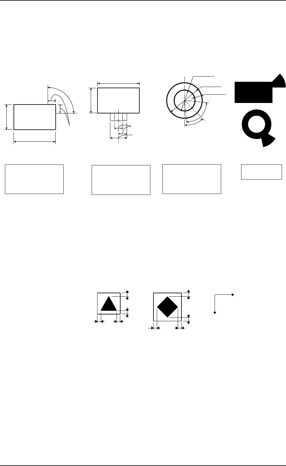
(Front Side of Machine)
45°
Pad Mark 45°
Range of Land Location
in Increments of 45° for
Pad mark
Pad Mark 90°
Range of Land Location
in Increments of 90° for
Pad mark
Range of Land Location
for Through Hole
(45° at the bottom right
of the hole)
Examples of Land
Locations
(Front Side of Machine)
(Front Side of Machine)
(Front Side of Machine)
2. Pattern Program
(2) Material
• Copper Leaf
(Au and Ni plating possible but mirror surfaces cannot be used.)
• Solder Plating (Consult our sales personnel.)
• Solder Leveler (Consult our sales personnel.)
(3) Specifications of Lines extended from a Pad Mark or a Through Hole
(Unit: mm)
1.0
X
Y
1.0
1.0
1.0
1.01.0
1.0
1.0
Unit: mm
(Front Side of Machine)
Example:
Fig. 2.28
(c) The shape of P.C.B. (a cutout, a punched hole), the exter-
nal elements (light reflected from a structure, light emitted
from an external device, etc.) may sometimes interfere with
recognition. Consult our sales personnel for details.
(d) A fiducial mark should make ample contrast with the sur-
roundings. (To prevent false recognition)
(e) Anything resembling a pattern similar to a fiducial mark
should not exist in the designated window. If one exists, it
may cause false recognition.
(f) A test may be required when the fiducial mark cannot be
recognized because of the extreme warpage of the P.C.B.
Fig. 2.27
Notes: (a) A through hole or a pad mark should have only one land
which is directed in increments of 45°. Consult our sales
personnel for details (dimensions, etc.).
(b) A copper leaf, a resist, a coating, a silk print, and a punched
hole should not exist in the range of 1.0 mm in both X and
Y directions from the outermost edges of a fiducial mark.
They may cause false recognition.
9910-001 2-31 Tg0247-PM-PM