2OM-1064-002.pdf - 第15页
2. Pattern Program 2.1 P A TTERN PROGRAM Display When the [P A TTERN PROGRAMMING] key is pressed at the “DA T A EDIT” display , the following display appears on the screen. 2. Pattern Program Fig. 2.1 *1 Number of Regist…

1. Scope of Pattern Program
The pattern program data is indispensable because the automatic operation is
controlled by the data when performed with this machine.
Note: Pattern program data can be edited on machine side. However, it is
recommended that pattern program data be edited, using a program-
ming device (option).
Pattern program data is composed of the following.
Operation Data
The operation data takes a role to summarize the pattern program data and is
composed of items such as “P.C.B. Size”, “Placement Mode”, “Designation of
Overall P.E.C. Recognition Mode”.
Refer to “2.3 OPERATION DATA Display of Section 2” for details.
Set-Up Data
This data is used to determine whether or not the conveyor width automatic
set-up operation should be performed sequentially with the [MOVE] button
(performed when the [MOVE] button is pressed) during program change op-
eration.
To implement the automatic set-up operation, set “ON” in the “CONVEYOR
WIDTH” data box at the “SET-UP DATA” display.
Refer to “2.4 SET-UP DATA Display of Section 2” for details.
Component Data
This data is used to designate which feeder position of the machine in order to
set various components to be placed on the P.C.B.
Feeder slot Nos. are allocated to some feeder blocks - “F101 to F139” belong
to the feeder section on Beam A side, “F201 to F239” to the feeder section on
Beam B side, “F301 to F599” (Option) to Tray L, and “F601 to F899” (Option)
to Tray R. A certain type (component ID) of components can be designated to
each feeder block.
Refer to “2.5 COMPONENT DATA Display of Section 2” for details.
Placement Data
This data is used to set parameters which select components (FDR Nos.) and
determine coordinates (X and Y) on the P.C.B. and directions (Z) of compo-
nent placement.
Data is created by allocating one step to one piece of component to be placed.
Refer to “2.6 Placement Data of Section 2” for details.
Steps for Data Creation
Be sure to follow the steps below to create various data.
(1) Create operation data.
(2) Create set-up data.
(3) Create component data.
(4) Create placement data.
1. Scope of Pattern Program
9910-001 2-2 Tg0247-PM-PM
2. Pattern Program
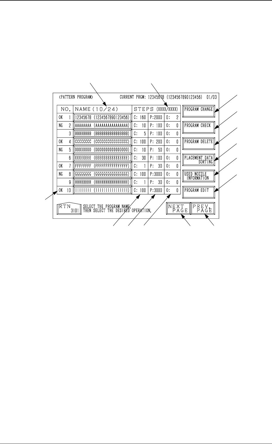
2.1 PATTERN PROGRAM Display
When the [PATTERN PROGRAMMING] key is pressed at the “DATA EDIT”
display, the following display appears on the screen.
2. Pattern Program
Fig. 2.1
*1 Number of Registered Programs (Number of Registered Pattern Programs)
The denominator 24 shows the maximum number of programs which can
be registered. The numerator shows the current number of registered pro-
grams.
In Fig. 2.1, the numerator shows that 10 pattern programs are registered.
Note: The retainable number of steps in memory will be limited accord-
ing to the regulatory conditions *1 and *2.
*2 Number of Used Steps (Memory)
The numerator “XXXX” shows the total of *3 “C Steps”, *4 “P Steps”,
and *5 “O Steps” used in each registered pattern program data.
The denominator “XXXX” shows the maximum retainable number of steps
in memory. The total number of steps cannot exceed this.
(Before creating data, check the remaining capacity “XXXX/XXXX”.)
*3 This shows the number of “FDR. No.” steps set in the component data.
*4 This shows the number of steps (P-No.) in the placement data.
*5 This shows the number of steps (O-No.) in the placement data.
*6 [NEXT PAGE] Key
When this key is pressed, the next page opens.
*1
*8
*9
*10
*14
*7
*6
*5
*3
*4
*12
*2
*11
*13
9910-001 2-3 Tg0247-PM-PM

2. Pattern Program
*7 [PREV. PAGE] Key
When this key is pressed, the previous page opens.
*8 [PROGRAM CHANGE] Key
Press this key to change the current program.
The “PROGRAM CHANGE” display opens.
(Refer to “3. Program Change of Section 4 in Volume 1” for details.)
*9 [PROGRAM CHECK] Key
Press this key to check the selected program.
*10 [PROGRAM DELETE] Key
Press this key to delete pattern program data.
*11 [PROGRAM EDIT] Key
Press this key to edit the selected program data. Another “PATTERN PRO-
GRAM EDIT” display opens for data editing.
*12 The results “OK” or “NG” of the program check operation is displayed
before each program No.
*13 [USED NOZZLE INFORMATION] Key
When this key is pressed, the “USED NOZZLE INFORMATION” dis-
play opens, indicating the nozzle IDs and quantity used in the pattern pro-
gram and the nozzles set in the nozzle stockers.
*14 [PLACEMENT DATA SORTING] Key
When this key is pressed, the “PLACEMENT DATA SORTING” display
appears on the screen, enabling the sorting of the component placement
order in the selected pattern program.
9910-001 2-4 Tg0247-PM-PM