2OM-1064-002.pdf - 第34页
Fig. 2.19 Note: When the global recognition is used together with the image recognition, both recognizing actions take place but the placement coordinates are corrected according to the result of the image recognition. P…
0004-002 2-21 Tg0247-PM-PM
2. Pattern Program
[2-Point Recognition]
Fig. 2.16
• Specify fiducial mark positions so that one fiducial mark is
kept as diagonally away from the other as possible.
Note: Avoid fiducial mark positions where the X and Y ele-
ments are the same. See Fig. 2.17 below.
Fig. 2.17
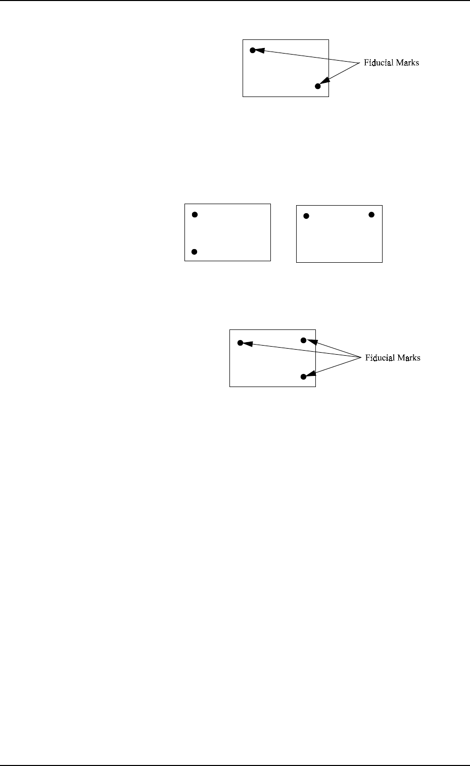
[3-Point Recognition]
Fig. 2.18
• Specify fiducial mark positions so that the triangle area
formed by connecting the three points (three fiducial marks)
becomes as large as possible.
Note: When any two of the three fiducial marks are desig-
nated to be positioned as close as possible to each other,
the results of the correction will be almost the same as
“2-Point Recognition” because the bend, expansion,
etc., of P.C.B. are detected as even occupants of the X
and Y elements.
In other words, the bend, expansion, etc., of P.C.B. oc-
cupying the X and Y elements unevenly will cause
wrong correction result.
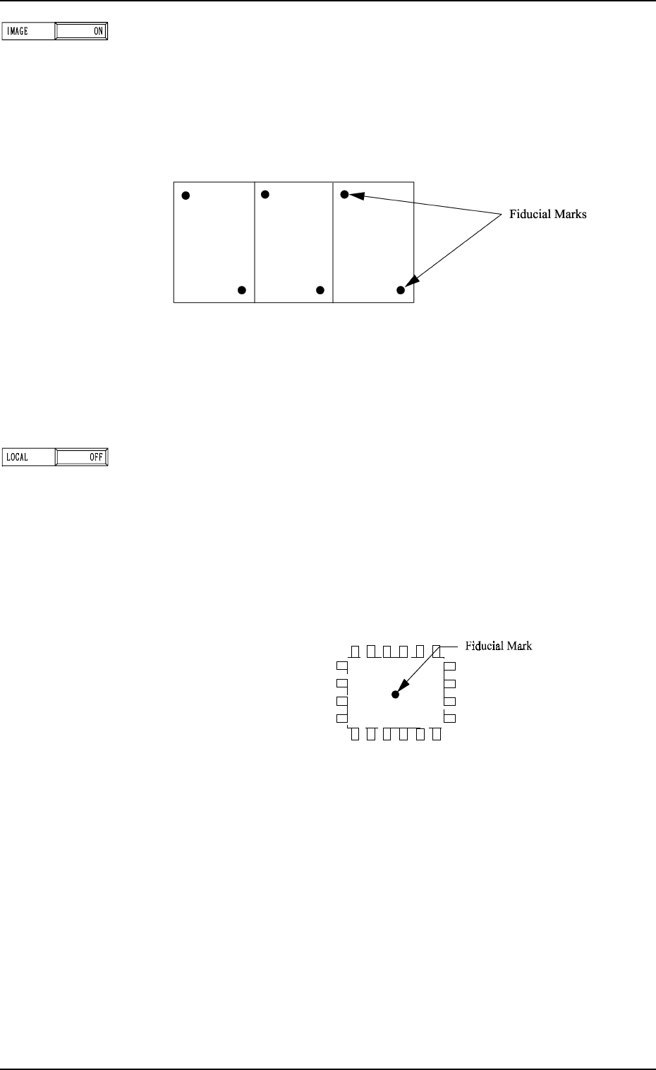
Fig. 2.19
Note: When the global recognition is used together with the
image recognition, both recognizing actions take place
but the placement coordinates are corrected according
to the result of the image recognition.
P.E.C. RECOGNITION MODE LOCAL
Set one of the following options to determine whether or not
the fiducial mark on each component placement point should
be recognized.
“OFF”
“ON”
1PT.: Put a fiducial mark on the center of component place-
ment point or a desired point around the center.
P.E.C. RECOGNITION MODE IMAGE
Set one of the following options to determine whether or not
the P.E.C. image recognition function should be performed.
“OFF”
“ON”
Note: The coordinates and mark data of a fiducial mark are
designated in the placement data (V).
2. Pattern Program
0004-002 2-22 Tg0247-PM-PM
Fig. 2.20
9910-001 2-23 Tg0247-PM-PM
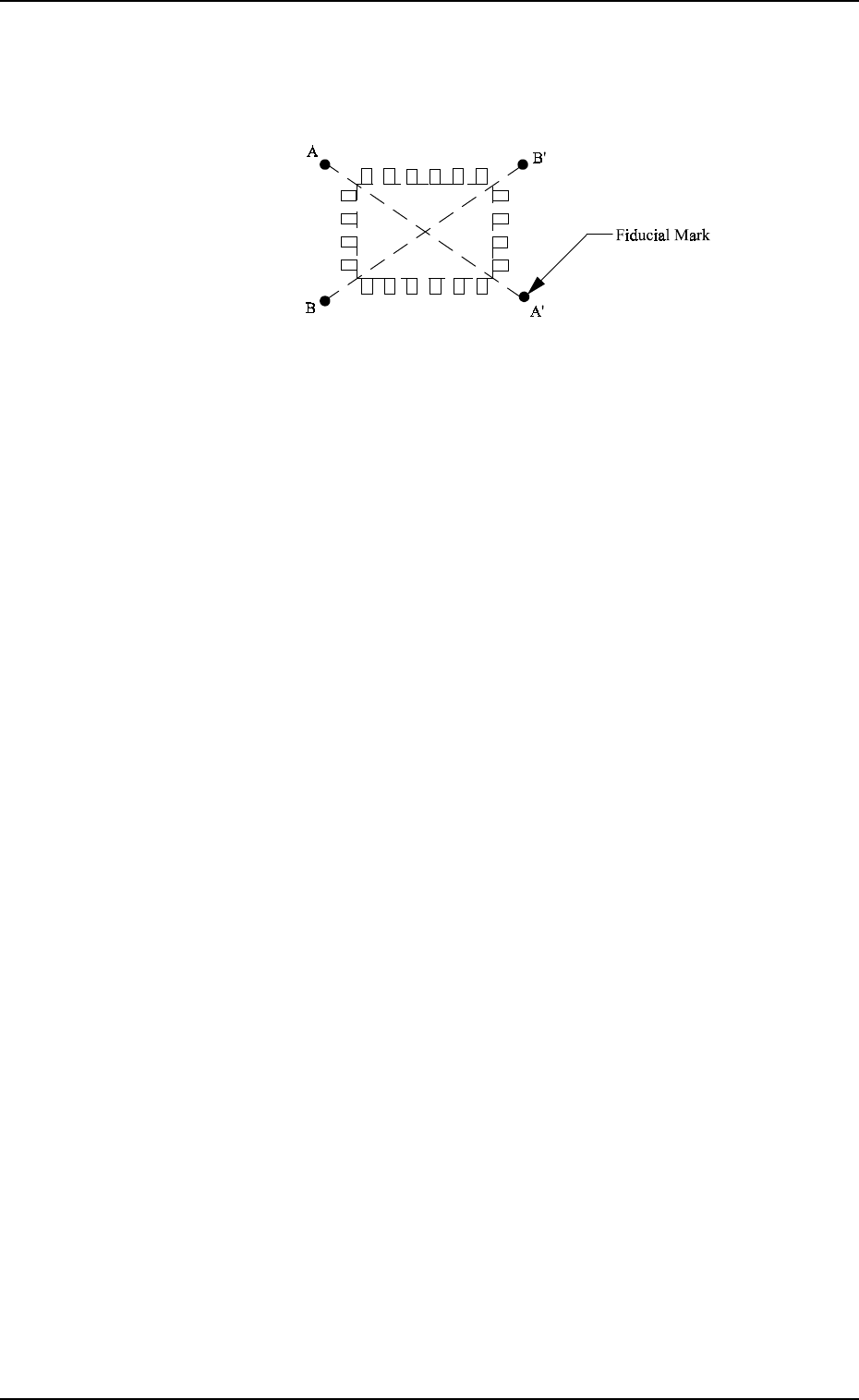
2PT.: It is recommended that two points (fiducial marks)
should be located symmetrically on both sides of the
center of the placement position.
(A-A’, B-B’)
2. Pattern Program
Fig. 2.21
When “ON” is set in the data box, the deviation of each com-
ponent placement point can be corrected.
Note: The coordinates and mark data of a fiducial mark are
designated in the placement data (V).