2OM-1064-002.pdf - 第75页
2.6.3 PLACEMENT DA T A (O) Display [Repetitive Placement Data] When the [DA T A EDIT] key is pressed at the “PLACEMENT DA T A (P) U01” display (Fig. 2.45-1 or Fig. 2.45-2), the follwing display appears on the screen. A l…

9910-001 2-62 Tg0247-PM-PM
C
Set a control command.
“-” : This command specifies the steps as component placement.
“S” : This command invalidates the steps specified as component place-
ment, bypassing the specified steps.
“C” : This command invalidates the steps specified as component place-
ment data.
This applies only to the component placement machine.
Note: When control command “S” or “C” is entered in the step P-
0000, the whole placement data is bypassed.
“D” : This command handles the steps as those used for component place-
ment.
(Step invalidating command for a glue dispenser)
“E” : This command shows the end of standard placement data.
(No “O” Data: Not a repetitive pattern program)
“P” : This command shows the end of basic multi-unit P.C.B. when com-
ponents are placed on the repetitive patterns in normal sequence.
When no O-NO step is created, a data error occurs.
“Q”: This command shows the end of basic multi-unit P.C.B. when com-
ponents are placed on the repetitive patterns in reverse sequence.
When no O-NO step is created, a data error occurs.
“B” : This shows the step where the coordinates of a bad mark are en-
tered.
Do not set this command in any step other than P-0001.
Note: When “OPTIONAL” is set in the “MODE” text box of the
label “UNIT PCB B.B.R.”, enter coordinates at the “PLACE-
MENT DATA (O)” display.
“0” “1” “2” “3” “4” “5” “6” “7” “8” “9”
When there are some factors which cause the reduction of tact time
for the nozzle change operation and tall component placement, etc.,
in the unit P.C.B.’s in the repetitive pattern program where “P” or
“Q” is set at the end of the placement data (P) and the normal place-
ment sequence for unit P.C.B.’s is taken to place component on the
unit P.C.B.’s, such factors will increase. In order to avoid this, these
commands are used to take countermeasures (priority sorting func-
tion).
When multi-unit P.C.B.’s or P.C.B.’s having multi-model repetitive
patterns (for Pn application) are produced, placing components on
specified areas of unit P.C.B.’s may improve productivity instead of
placing components on one unit P.C.B. by another.
Refer to “3.2.6 Placement Data for Priority Sorting Function, and
3.2.7 Priority Sorting Application for Multi-Model Repetitive Pat-
terns of Section 2” for details.
COMMENT
A comment can be entered for each step No.
A reference No. printed on the upper surface of P.C.B. can be entered as a
comment.
Up to 8 characters can be entered.
Any operation is not affected by the comment.
COMPONENT ID
The component ID set in the data field labeled “FDR” is displayed. This ID
corresponds with the ID set in the data field labeled “FDR NO” in the com-
ponent data.
2. Pattern Program
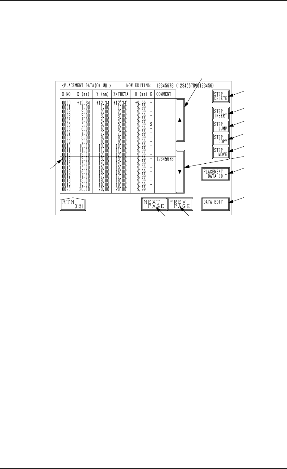
2.6.3 PLACEMENT DATA (O) Display [Repetitive Placement Data]
When the [DATA EDIT] key is pressed at the “PLACEMENT DATA (P) U01”
display (Fig. 2.45-1 or Fig. 2.45-2), the follwing display appears on the screen.
A list of repetitive placement data is displayed.
Parameters can be edited at the display opened by pressing the [DATA EDIT]
key *13.
Fig. 2.46
*1
*5
*4
*8
*9
*10
*11
*12
*16
*13
*3
*2
2. Pattern Program
For *1 to *15, refer to the description in “2.6.2 Placement Data (P) Display
[Component Placement Data]”.
*16 [PLACEMENT DATA EDIT] Key
When this key is pressed, the “PLACEMENT DATA (P) U01” display
appears on the screen.
0004-002 2-63 Tg0247-PM-PM
Description of Parameters
O-NO
This shows the step Nos. of repetitive placement data.
(The step “O-0000” always appears on the screen.)
• Enter “0” (zero) in all data fields and “-” as a control command in step
“O-0000”.
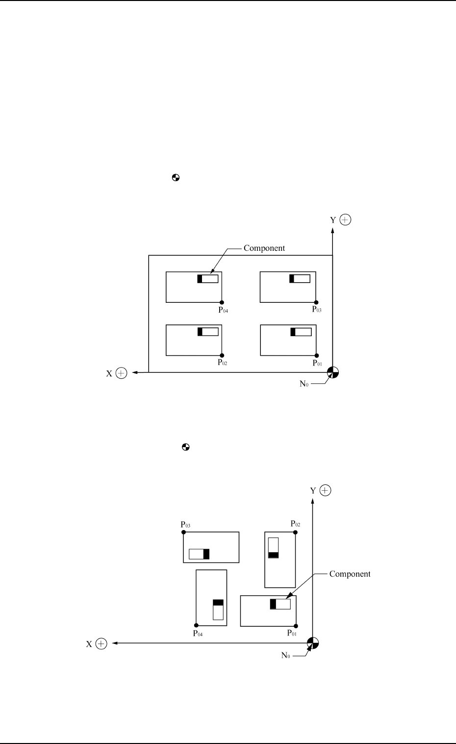
X (mm) and Y (mm)
Set the coordinates (X and Y) from the placement data reference to the
origin for each pattern.
Ref.: The pattern origin refers to the coordinates for the multi-unit P.C.B.
which forms repetitive patterns.
N
0
: The center of mark is Placement Data Reference.
P
01
: Pattern Origin of Pattern 1
P
02
: Pattern Origin of Pattern 2
P
03
: Pattern Origin of Pattern 3
P
04
: Pattern Origin of Pattern 4
Pattern 1: 0°
Pattern 2: 90°
Pattern 3: 180°
Pattern 4: 270°
N
0
: The center of mark is Placement Data Reference.
P
01
: Pattern Origin of Pattern 1
P
02
: Pattern Origin of Pattern 2
P
03
: Pattern Origin of Pattern 3
P
04
: Pattern Origin of Pattern 4
0004-002 2-64 Tg0247-PM-PM
2. Pattern Program
Z=THETA (Angle)
Set the angle of each pattern.
• 0°, 90°, 180°, or 270° can be set as a parameter.