2OM-1064-002.pdf - 第203页
7. NOZZLE STOCKER OFFSET Display NOZZLE STOCKER [B1] (BEAM-A) The set of fset data is used to adjust the positional deviations based on the design dimensions representing the nozzle stocker unit position viewed from the …
7. NOZZLE STOCKER OFFSET Display
NOZZLE STOCKER OFFSET (For Individual Addresses)
NOZZLE STOCKER [A1] (BEAM-A)
The set offset data is used to adjust the positional deviations based on the
design dimensions representing the nozzle stocker unit position viewed from
the X/Y coordinate system (PL-XY: Origin P0) for P.C.B. positioning.
The values based on the PL-XY coordinate system must be entered in the
data boxes.
Set the values which represent the positional deviations of Nozzle Stocker
A1 based on Beam A for each individual addresses.
X (mm) and Y (mm)
When offset parameters are set with a plus (+) sign, the nozzle change
directions are changed to “X (+)” and “Y (+)” shown in the figure.
9910-001 5-32 Tg0247-PM-PM
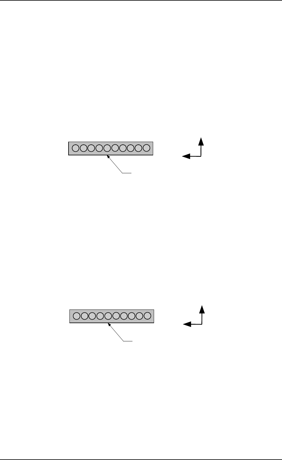
Nozzle Stocker A1
1
10
Y(+)
X(+)
Nozzle Stocker A1
1
10
Y(+)
X(+)
NOZZLE STOCKER [A1] (BEAM-B)
The set offset data is used to adjust the positional deviations based on the
design dimensions representing the nozzle stocker unit position viewed from
the X/Y coordinate system (PL-XY: Origin P0) for P.C.B. positioning.
The values based on the PL-XY coordinate system must be entered in the
data boxes.
Set the values which represent the positional deviations of Nozzle Stocker
A1 based on Beam B for each individual addresses.
X (mm) and Y (mm)
When offset parameters are set with a plus (+) sign, the nozzle change
directions are changed to “X (+)” and “Y (+)” shown in the figure.
7. NOZZLE STOCKER OFFSET Display
NOZZLE STOCKER [B1] (BEAM-A)
The set offset data is used to adjust the positional deviations based on the
design dimensions representing the nozzle stocker unit position viewed from
the X/Y coordinate system (PL-XY: Origin P0) for P.C.B. positioning.
The values based on the PL-XY coordinate system must be entered in the
data boxes.
Set the values which represent the positional deviations of Nozzle Stocker
B1 based on Beam A for each individual addresses.
X (mm) and Y (mm)
When offset parameters are set with a plus (+) sign, the nozzle change
directions are changed to “X (+)” and “Y (+)” shown in the figure.
9910-001 5-33 Tg0247-PM-PM
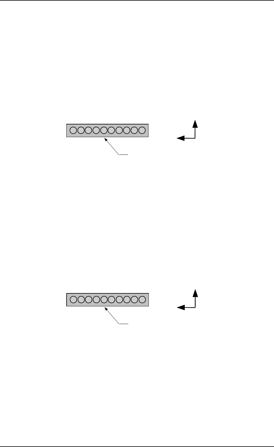
1
10
Y(+)
X(+)
Nozzle Stocker B1
1
10
Y(+)
X(+)
Nozzle Stocker B1
NOZZLE STOCKER [B1] (BEAM-B)
The set offset data is used to adjust the positional deviations based on
the design dimensions representing the nozzle stocker unit position
viewed from the X/Y coordinate system (PL-XY: Origin P0) for P.C.B.
positioning.
The values based on the PL-XY coordinate system must be entered in
the data boxes.
Set the values which represent the positional deviations of Nozzle
Stocker B1 based on Beam B for each individual addresses.
X (mm) and Y (mm)
When offset parameters are set with a plus (+) sign, the nozzle change
directions are changed to “X (+)” and “Y (+)” shown in the figure.
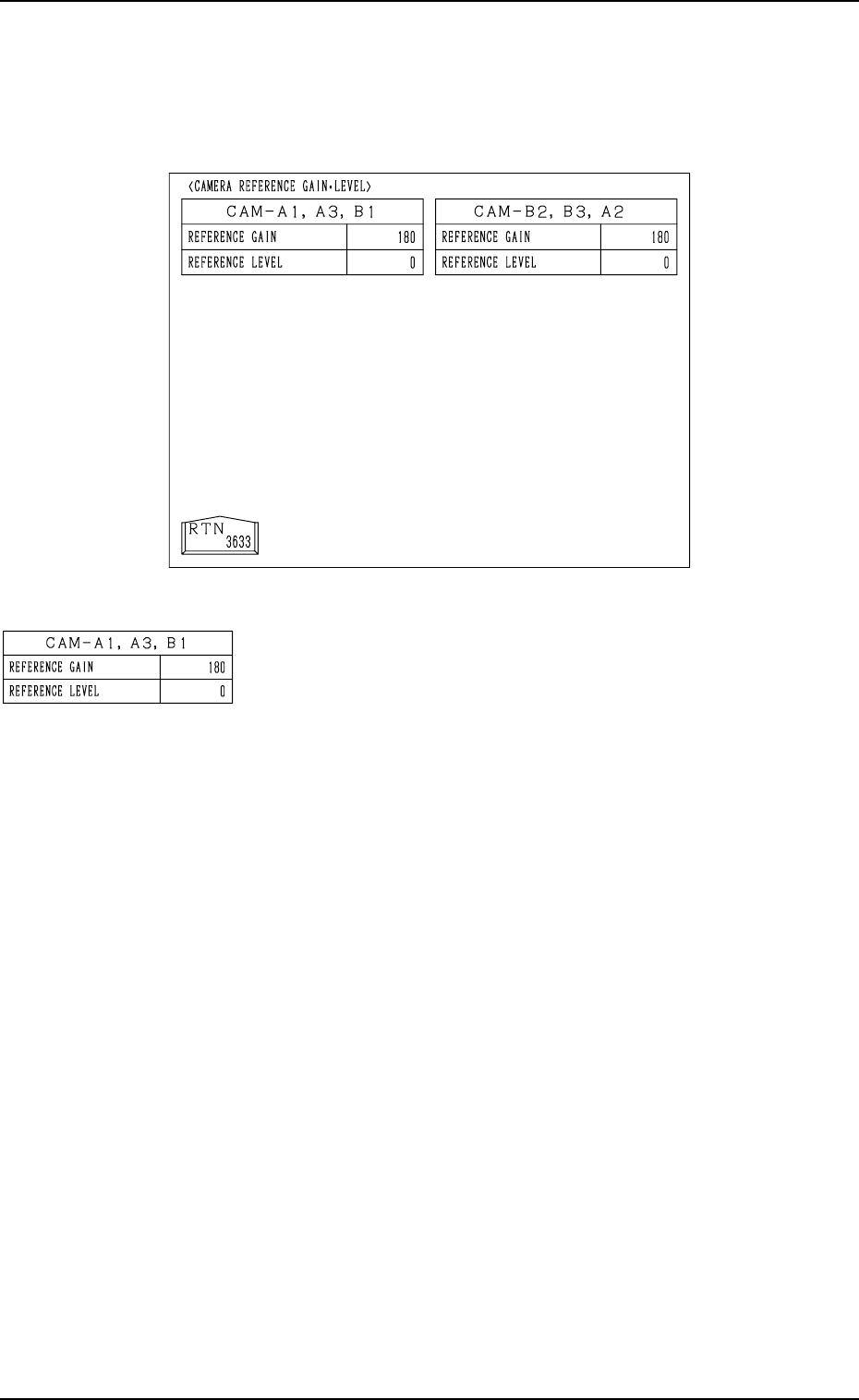
Fig. 5.32
REFERENCE GAIN/LEVEL: Used commonly for each cam-
era
All parameters are set through the automatic teaching opera-
tion.
Note: This is just an information display (editing impossible).
9910-001 5-34 Tg0247-PM-PM
8. CAMERA REFERENCE GAIN · LEVEL Display
8. CAMERA REFERENCE GAIN · LEVEL Display
When the [CAMERA REFERENCE GAIN/LEVEL] key is pressed at the “OFF-
SET DATA” display, the following display appears on the screen.