2OM-1064-002.pdf - 第30页
P .C.B. LOCA TE DA TUM “OUTSIDE” or “HOLE” can be set in the data box. In normal cases, “OUTSIDE” must be set. When “HOLE” is set, the reference pin for machine position- ing is automatically aligned with the P .C.B. hol…
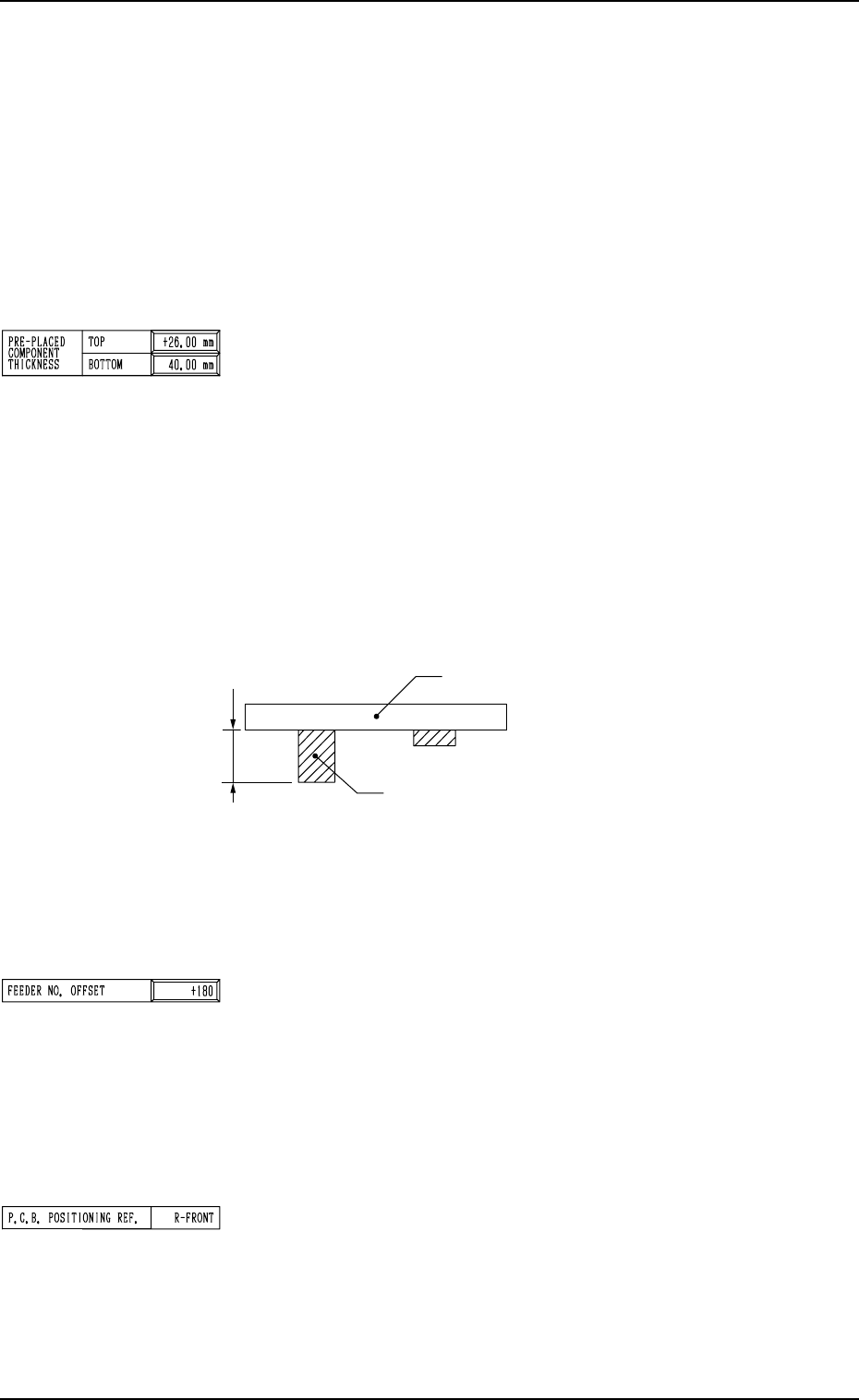
Fig. 2.14
• Data Input Range: 0 to 30.00 mm
Note: When the thickness of a previously-placed component
is more than 30.00 mm and 40.00 mm or less, consult
our sales personnel for details.
FEEDER NO. OFFSET : Reserved Data
The set offset data is used to shift the feeder allocation on the
feeder base.
Note: The multi-layer tray unit is not affected by the set pa-
rameter.
Set the offset value for the component allocation to the feeder
base.
The set parameter is added to the feeder slot No. (FDR NO.)
designated in the placement data.
P.C.B. POSITIONING REF.
Shown is the reference of placement coordinates.
L-BACK : Left Back Reference
L-FRONT : Left Front Reference
R-FRONT : Right Front Reference
R-BACK : Right Back Reference
Note: No editing is available.
The maximum thickness of the placed component is managed
on the machine side to automatically change the component
transfer level every time a component is placed, avoiding any
interference between the picked and placed components.
• It is advisable that shorter components be placed before the
tallest one.
Note: When P.C.B.’s have previously-placed components and
“0” (no previously-placed components) is set in the
data box, the picked components may interfere with
the placed components.
• Data Input Range: 0 to 25.40 mm
BOTTOM
When some components are placed previously (in advance)
on the back of a P.C.B. in the upstream line (input machine,
etc.) and the P.C.B. is already transferred to the machine, be
sure to enter the thickness of the highest component of all in
the data box.
The set parameter is used to determine the position (elevation)
of the first backup table when the P.C.B. is transferred to the
P.C.B. positioning section.
Note: When P.C.B.’s have previously-placed components and
“0” (no previously-placed components) is set in the data
box, the support pins may interfere with the previously-
placed components while the P.C.B. is being transferred
to the P.C.B. positioning section.
2. Pattern Program
P.C.B.
Tallest Previously-Placed Component
9910-001 2-17 Tg0247-PM-PM
P.C.B. LOCATE
DATUM
“OUTSIDE” or “HOLE” can be set in the data box.
In normal cases, “OUTSIDE” must be set.
When “HOLE” is set, the reference pin for machine position-
ing is automatically aligned with the P.C.B. hole position.
Note: The above positioning method may not work, depend-
ing on the combination of the P.C.B. flow direction and
the positioning reference position and the value set in
the “X” data box of the label “P.C.B. SIZE”.
Please contact us when the "Hole" reference is used.
SEQUENCE
“STANDARD” , “MODE1” or “MODE2” can be set in the
data box.
STANDARD : The P.C.B. positioning is completed after the
clamp plates have moved up, have stopped at
the position where the P.C.B. is lifted by 0.5
mm, the P.C.B. locating side clamp (Y pusher)
has moved forward, and the clamp plates have
moved up.
MODE1 : The P.C.B. positioning is completed when the
clamp plates have moved up completely.
(No Movement of P.C.B. Locating Side
Clamp)
MODE2 : The P.C.B. positioning is completed after the
clamp plates have moved up, have stopped at
the position where the P.C.B. is lifted by 0.5
mm, the P.C.B. locating side clamp (Y pusher)
has moved forward, the Y pusher has moved
backward, the clamp plates have moved up,
and the Y pusher has moved forward.
Third Page
RECOVERY BLOCK
In the case of block-specified operation, components are placed
starting with the smallest block No.
Unless all components in the specified block are placed com-
pletely, component placement operation does not take place
for the subsequent block.
(When a recovery event occurs, component placement opera-
tion does not take place until the recovery is completed.)
Block Nos.: 0 to 9 specified as a control command “C” of “P-
No.” in the pattern program
“OFF” or “ON” can be set in the data box.
OFF : Set this in the data box when the recovery regulation
is not required.
ON : Set this in the data box when the recovery regulation
is required.
Example of Setting
• To place small components on the placed large ones
• To place small components and attach covers to them
• Others
2. Pattern Program
9910-001 2-18 Tg0247-PM-PM
P.E.C. RECOG. TIMING
Set one of the following options to specify the timing of P.E.C.
recognition implementation.
“AFTER PU”
“BEFORE PU”
It is recommended that “AFTER PU” should be selected in
normal cases.
[AFTER PU]
The P.E.C. recognition function is performed after a com-
ponent is picked up.
This parameter should be selected when the following re-
quirements are met at the implementation of the P.E.C. rec-
ognition function.
• The dimensions of the component to be picked up should
be “40 × 40 mm” or less. (Approximate Values)
• The component should not be in the view of the P.E.C.
recognition camera by the pick-up location adjustment
function.
2.3.2 Operation Data (P.E.C. Recognition)
Second Page
P.E.C. RECOGNITION
Set one of the following options to determine whether or not
the P.E.C. recognition function should be used.
“ON”
“OFF”
P.E.C. RECOGNITION BEAM
Set one of the following options to determine which beam
should be used for the global and image recognition functions.
“BEAM-A”
“BEAM-B”
“BOTH-BEAM”
“BEAM-A”: Select this when only Beam A is used to
place the components.
“BEAM-B”: Select this when only Beam B is used to
place the components.
“BOTH-BEAM”: Select this when both Beam A and B are
used to place the components.
2. Pattern Program
0308-002 2-19 Tg0247-PM-PM
Reference
As for the local recognition function, the P.E.C. recognition is
made using the camera on the beam where components are
placed regardless of the parameter set in the data box.