2OM-1064-002.pdf - 第197页
7. NOZZLE STOCKER OFFSET Display • This offset data is used to adjust the position of the nozzle stocker unit based on “P .C.B. Positioning Reference: P0”. When the [NOZZLE STOCKER OFFSET] key is pressed at the “OFFSET D…
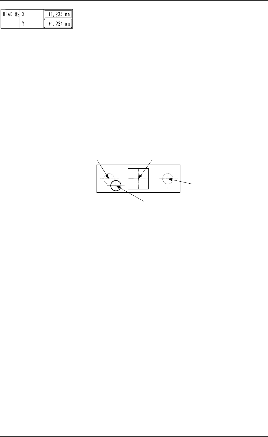
BEAM B HEAD #2, X (Horizontal), Y (Vertical)
This offset data is used to set the distance between the scan-
ning coordinate center (actual position) of the P.E.C. camera
on Beam B and the rotational center of Head #2. The distances
deviating from the design values must be entered in each data
box.
The parameters must be those viewed in the X/Y coordinate
system (PL-XY) for P.C.B. positioning.
• Design Values (distances between the center of P.E.C. cam-
era on Beam B and the rotational center of Head #2)
X : +54.000 mm
Y : +0.000 mm
When the rotational center of Head #2 is actually located at
the position shown in the figure below, the offset param-
eters representing the X (horizontal) and Y (vertical) must
be provided with plus (+) signs.
0004-002 5-26 Tg0247-PM-PM
6. HEAD CENTER OFFSET Display
Center of P.E.C. Camera on Beam B
Rotational Center (Design Position)
of Head #2 on Beam B
Actual Rotational Center of Head #2 on Beam B
Rotational Center (Design Position)
of Head #1 on Beam B
(Front Side of Machine)
Top View
Fig. 5.30
This offset data is automatically calculated through teaching
operation which is performed, using the jig component sta-
tioned at the teaching plate inside the machine.
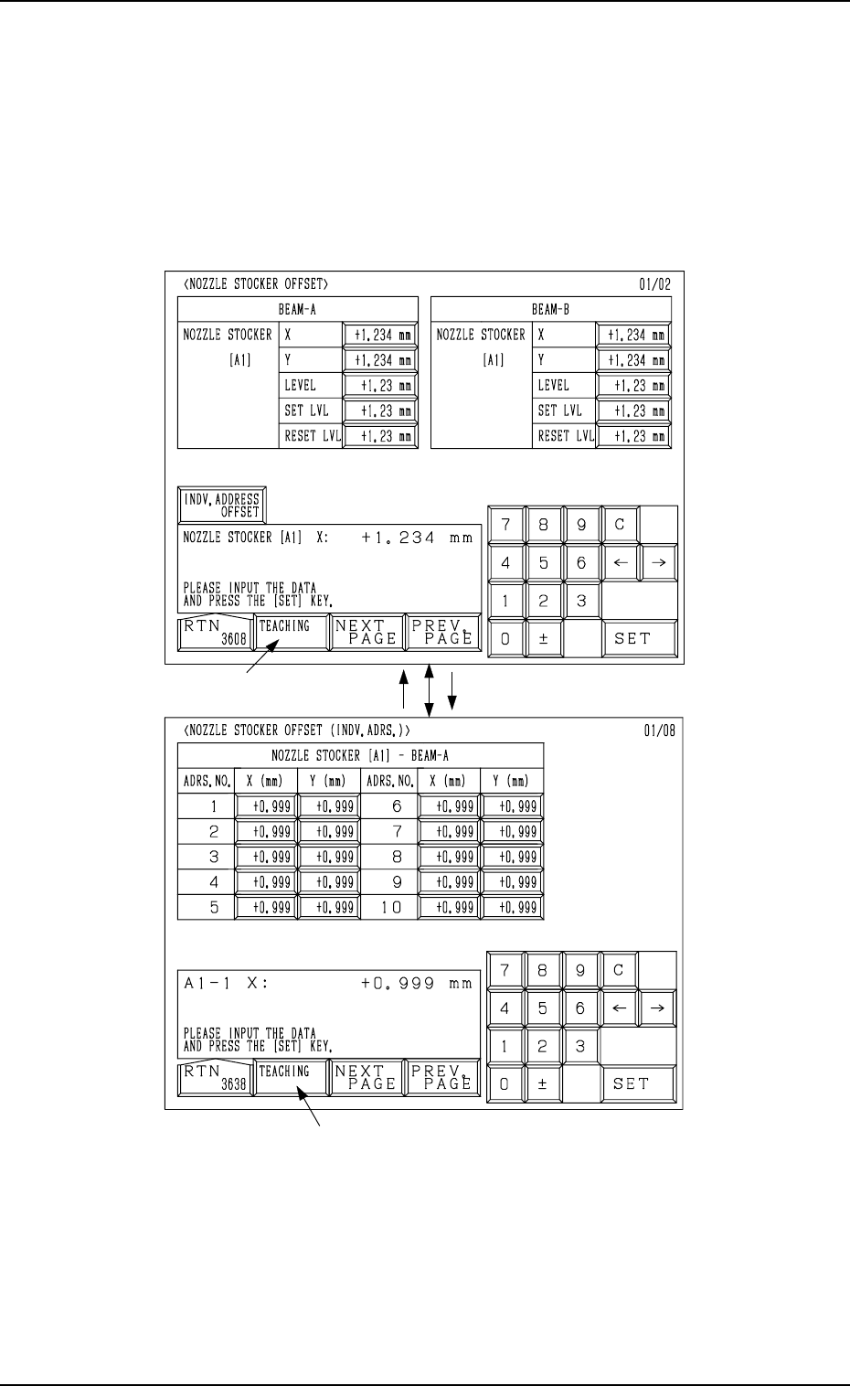
7. NOZZLE STOCKER OFFSET Display
• This offset data is used to adjust the position of the nozzle stocker unit
based on “P.C.B. Positioning Reference: P0”.
When the [NOZZLE STOCKER OFFSET] key is pressed at the “OFFSET
DATA” display, the following display appears on the screen.
Every time the [NEXT PAGE] or the [PREV. PAGE] key is pressed, another or
previous page appears on the screen.
Fig. 5.31-1
Fig. 5.31-2
*1
[INDV. ADDRESS OFFSET] Key[RTN] Key
*1
7. NOZZLE STOCKER OFFSET Display
Ref.: When the [TEACHING] key *1 is pressed, the “UNIT MANUAL
ALIGNMENT TEACH” display appears on the screen.
Refer to “6.8.5 Nozzle Stocker Offset of Section 3 in Volume 4” for
details.
9910-001 5-27 Tg0247-PM-PM
7. NOZZLE STOCKER OFFSET Display
9910-001 5-28 Tg0247-PM-PM
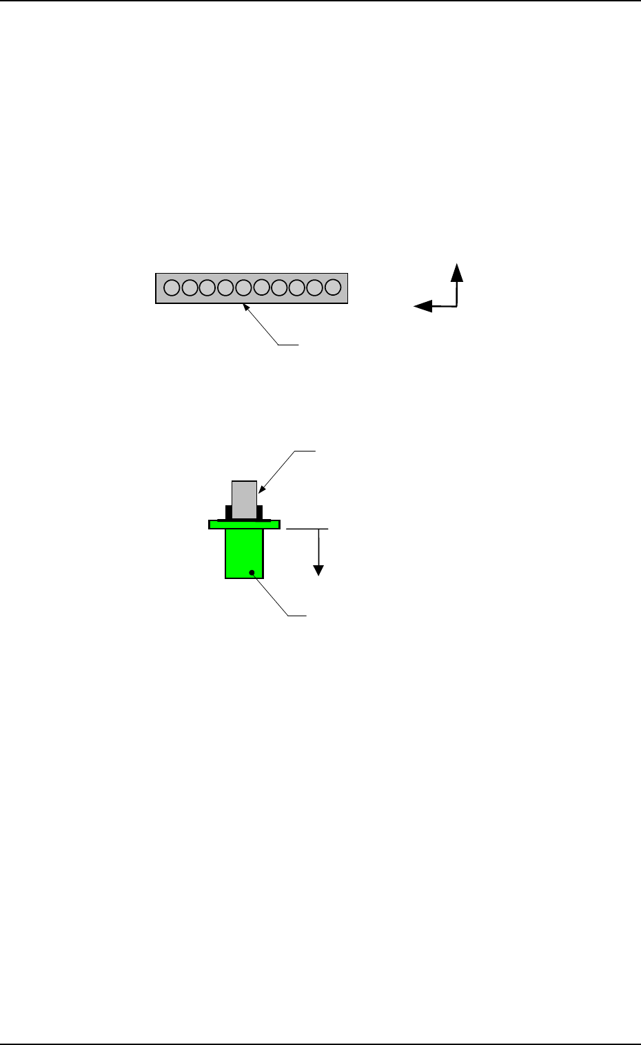
BEAM-A NOZZLE STOCKER [A1]
The set offset data is used to adjust the positional deviations based on the
design dimensions representing the nozzle stocker unit position viewed from
the X/Y coordinate system (PL-XY: Origin P0) for P.C.B. positioning.
The values based on the PL-XY coordinate system must be entered in the
data boxes.
Set the values which represent the positional deviations of Nozzle Stocker
A1 based on Beam A.
X (Horizontal) and Y (Vertical)
When offset parameters are set with a plus (+) sign, the nozzle change
directions are changed to “X (+)” and “Y (+)” shown in the figure.
L(+)
Nozzle
Nozzle Clamp Section
Nozzle Stocker A1
1
10
Y(+)
X(+)
LEVEL (Height)
When an offset parameter is set with a plus (+) sign, the nozzle change
direction is changed to “L (+)” shown in the figure, concluding that the
descending stroke has increased.
SET LVL
Set an offset value (offset in vertical (height) direction of the head) re-
quired when a nozzle is attached to the head.
(This is added to the parameter in the “LEVEL (Height)” data box.)
When an offset parameter is set with a plus (+) sign, the up/down shaft
descends, concluding that the descending stroke has increased.
RESET LVL
Set an offset value (offset in vertical (height) direction of the head) re-
quired when the nozzle is stored.
(This is added to the parameter in the “LEVEL (Height)” data box.)
When an offset parameter is set with a plus (+) sign, the up/down shaft
descends, concluding that the descending stroke has increased.
Note: As for the values to be set in the “X” and “Y” data boxes, align the
nozzle position manually at several places (1 through 10) and per-
form the measurement. Then, set the mean values in each data box.
When the nozzle is manually aligned only at one place, it may be
positioned at a place where the nozzle cannot be changed easily.