2OM-1064-002.pdf - 第158页
Fig. 3.5-4 P .C.B. TRANSFER-DIR. Set “L → R” or “R → L” in the data box to specify the P .C.B. transfer direction. • [L → R] P .C.B.’ s are transferred from left to right. • [R → L] P .C.B.’ s are transferred from right …
TIM-5100FL
P.C.B. Transfer Reference: Front Side of Machine
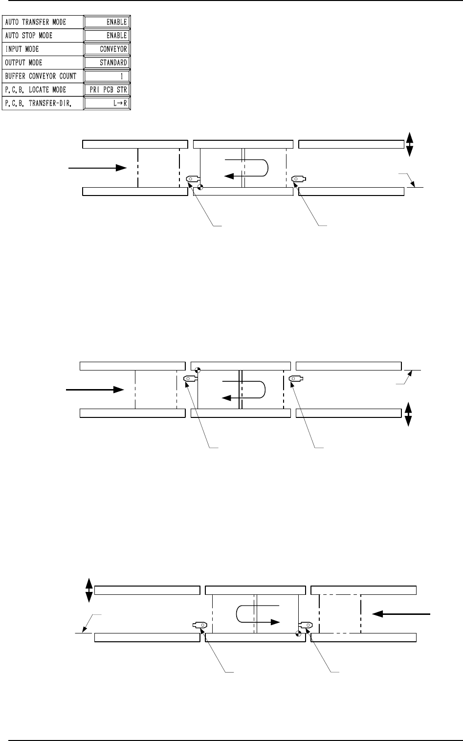
P.C.B. Transfer : L → R
P.C.B. Positioning Reference: L-FRONT
2. P.C.B. TRANSFER MODE SET-UP Display
A
L Conveyor
(Output Conveyor)
R Conveyor
(Input Conveyor)
L Conveyor
P.C.B. Stopper
R Conveyor
P.C.B. Stopper
P Conveyor
(P.C.B. Positioning Section)
P.C.B. Transfer
Reference
P.C.B.
P.C.B. Flow Direction
Movable
Side
Placement Reference
Placement Reference
R Conveyor
(Output Conveyor)
L Conveyor
(Input Conveyor)
L Conveyor
P.C.B. Stopper
R Conveyor
P.C.B. Stopper
P Conveyor
(P.C.B. Positioning Section)
P.C.B.
P.C.B. Flow Direction
Movable
Side
P.C.B. Transfer
Reference
A
Placement Reference
R Conveyor
(Output Conveyor)
L Conveyor
(Input Conveyor)
L Conveyor
P.C.B. Stopper
R Conveyor
P.C.B. Stopper
P Conveyor
(P.C.B. Positioning Section)
P.C.B. Transfer Reference
P.C.B.
P.C.B. Flow Direction
Movable
Side
A
Fig. 3.5-1
TIM-5100RL
P.C.B. Transfer Reference: Rear Side of Machine
P.C.B. Transfer : L → R
P.C.B. Positioning Reference: L-BACK
Fig. 3.5-2
TIM-5100FR
P.C.B. Transfer Reference: Front Side of Machine
P.C.B. Transfer : R → L
P.C.B. Positioning Reference: R-FRONT
Fig. 3.5-3
9910-001 3-9 Tg0247-PM-PM
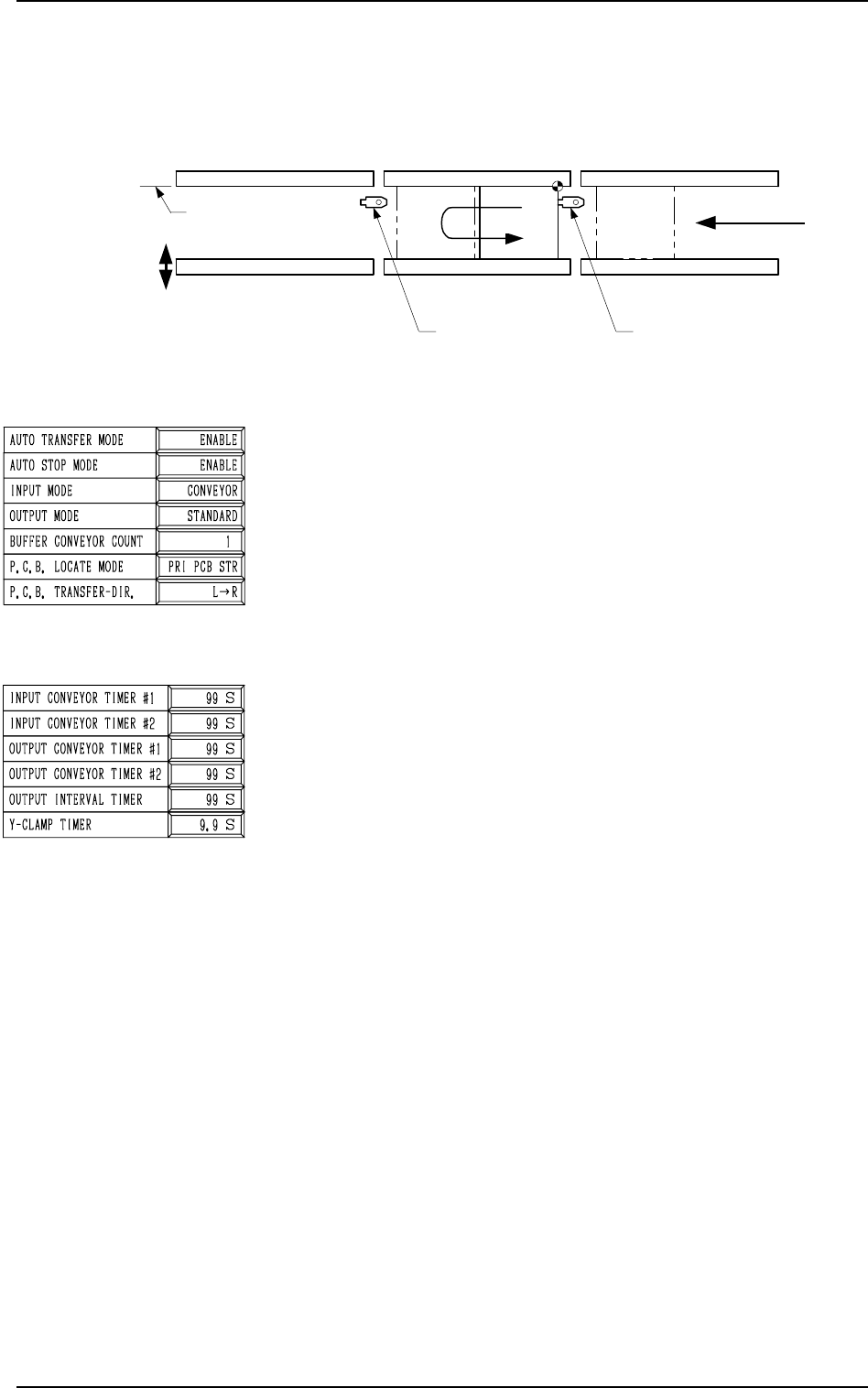
Fig. 3.5-4
P.C.B. TRANSFER-DIR.
Set “L → R” or “R → L” in the data box to specify the P.C.B.
transfer direction.
• [L → R]
P.C.B.’s are transferred from left to right.
• [R → L]
P.C.B.’s are transferred from right to left.
Note: Whenever the set parameter is changed, the zeroing
operation must be performed.
INPUT CONVEYOR TIMER #1
The operating time (P.C.B. reception from the input machine)
of the input conveyor can be limited by this timer.
This timer measures the operating time of the input conveyor
and is used to detect an interrupted P.C.B.
• Add 2 seconds (approx.) to the time required for P.C.B. re-
ception from the input machine and set.
• Data Input Range: 0 to 99 seconds
INPUT CONVEYOR TIMER #2
The operating time of the input conveyor can be limited by
this timer when a P.C.B. is transferred inside the machine by
the input conveyor.
This timer measures the operating time of the input conveyor
and is used to detect an interrupted P.C.B.
Note: This time is also used for the timer of EL/ER conveyor
(option).
• Data Input Range: 0 to 99 seconds
OUTPUT CONVEYOR TIMER #1
The operating time of the output conveyor can be limited by
this timer when a P.C.B. is received by the output machine.
• Add 2 seconds (approx.) to the time required for P.C.B. trans-
fer to the output machine and set.
• Data Input Range: 0 to 99 seconds
2. P.C.B. TRANSFER MODE SET-UP Display
TIM-5100RR
P.C.B. Transfer Reference: Rear Side of Machine
P.C.B. Transfer : R → L
P.C.B. Positioning Reference: R-BACK
A
L Conveyor
(Output Conveyor)
R Conveyor
(Input Conveyor)
L Conveyor
P.C.B. Stopper
R Conveyor
P.C.B. Stopper
P Conveyor
(P.C.B. Positioning Section)
P.C.B. Transfer
Reference
P.C.B.
P.C.B. Flow Direction
Movable
Side
Placement Reference
0103-003 3-10 Tg0247-PM-PM
OUTPUT CONVEYOR TIMER #2
The operating time of the output conveyor can be limited by
this timer when a P.C.B. is transferred inside the machine by
the output conveyor.
This timer measures the operating time of the output conveyor
and is used to detect an interrupted P.C.B.
Note: This time is also used for the timer of EL/ER conveyor
(option).
• Data Input Range:
0 to 99 seconds
Note: When “STANDARD” is set in the “OUTPUT MODE”
data box, the machine stops in an error condition after
this timer has reached the set time.
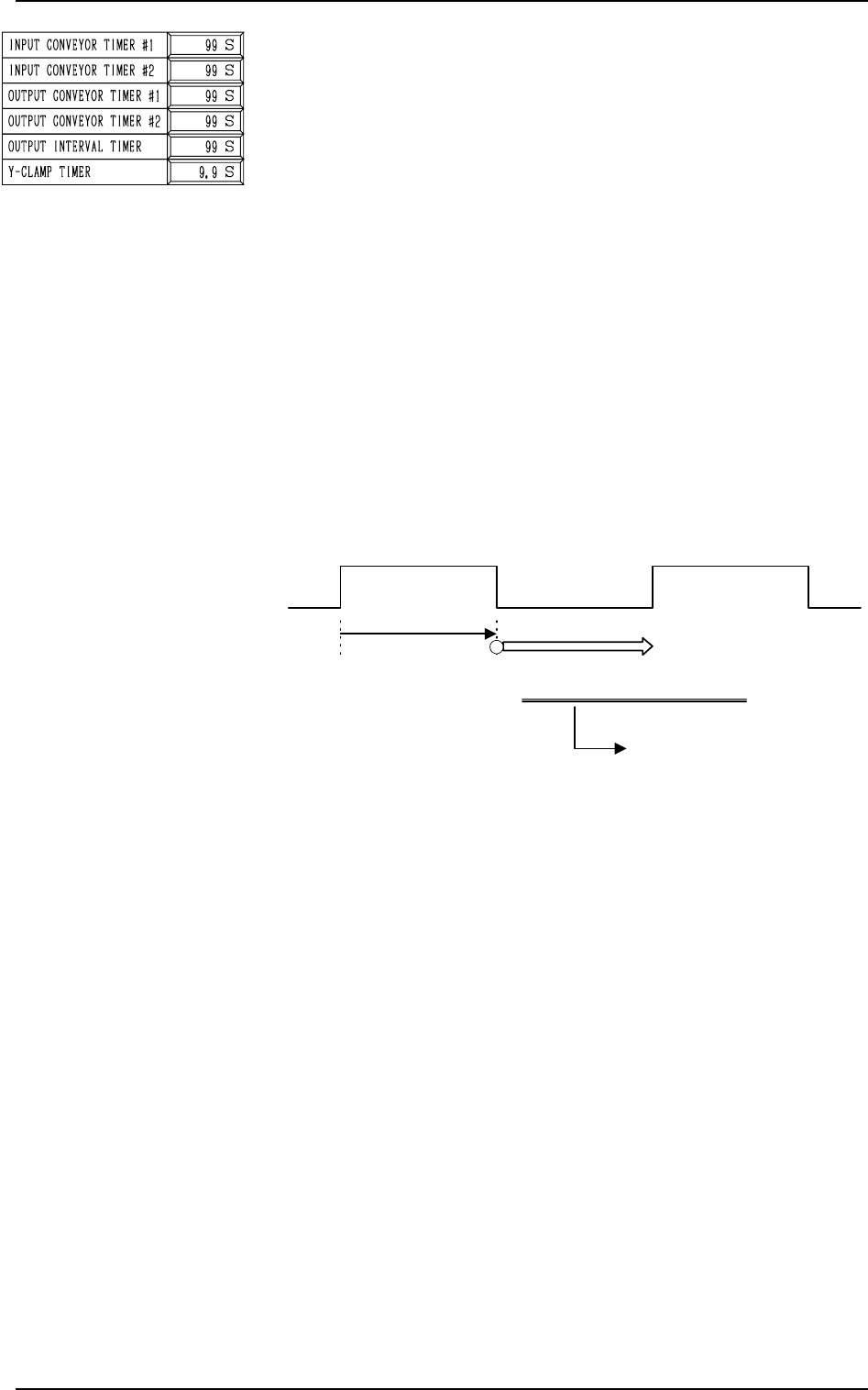
OUTPUT INTERVAL TIMER
When “INTERVAL” (P.C.B. output without handshaking) is
set in the “OUTPUT MODE” data box, this timer is used to
set an output interval time.
• Data Input Range: 0 to 99 seconds
2. P.C.B. TRANSFER MODE SET-UP Display
0103-003 3-11 Tg0247-PM-PM
Fig. 3.6
Y-CLAMP TIMER
Set a period of time during which the Y pusher moves forward
or backward for P.C.B. alignment in Y direction (horizontal
P.C.B. positioning). The set parameter is used commonly for
both forward and backward movements.
The Y pusher is not provided with any sensors for detection of
the forward or backward movement because the Y pusher
moves only a short distance. Therefore, the timing of move-
ment is controlled by the software-based timer.
• Default: 0.3 seconds
• Enter a period of time during which the Y alignment is
made completely.
• Whenever the speed of the forward or the backward move-
ment is adjusted, it is required to change the set parameter
to avoid any impact which may be given to a P.C.B. dur-
ing Y alignment.
• Data Input Range: 0 to 99 seconds
Note: When the parameter is too large, excessively long
time will be required for P.C.B. positioning or re-
leasing.
Output Conveyor ON
Transfer of Subsequent P.C.B.
Controlled by the
output conveyor
timer #1
Output Interval Timer
This timer gives an interval
time until the subsequent
P.C.B. is transferred.