2OM-1064-002.pdf - 第49页
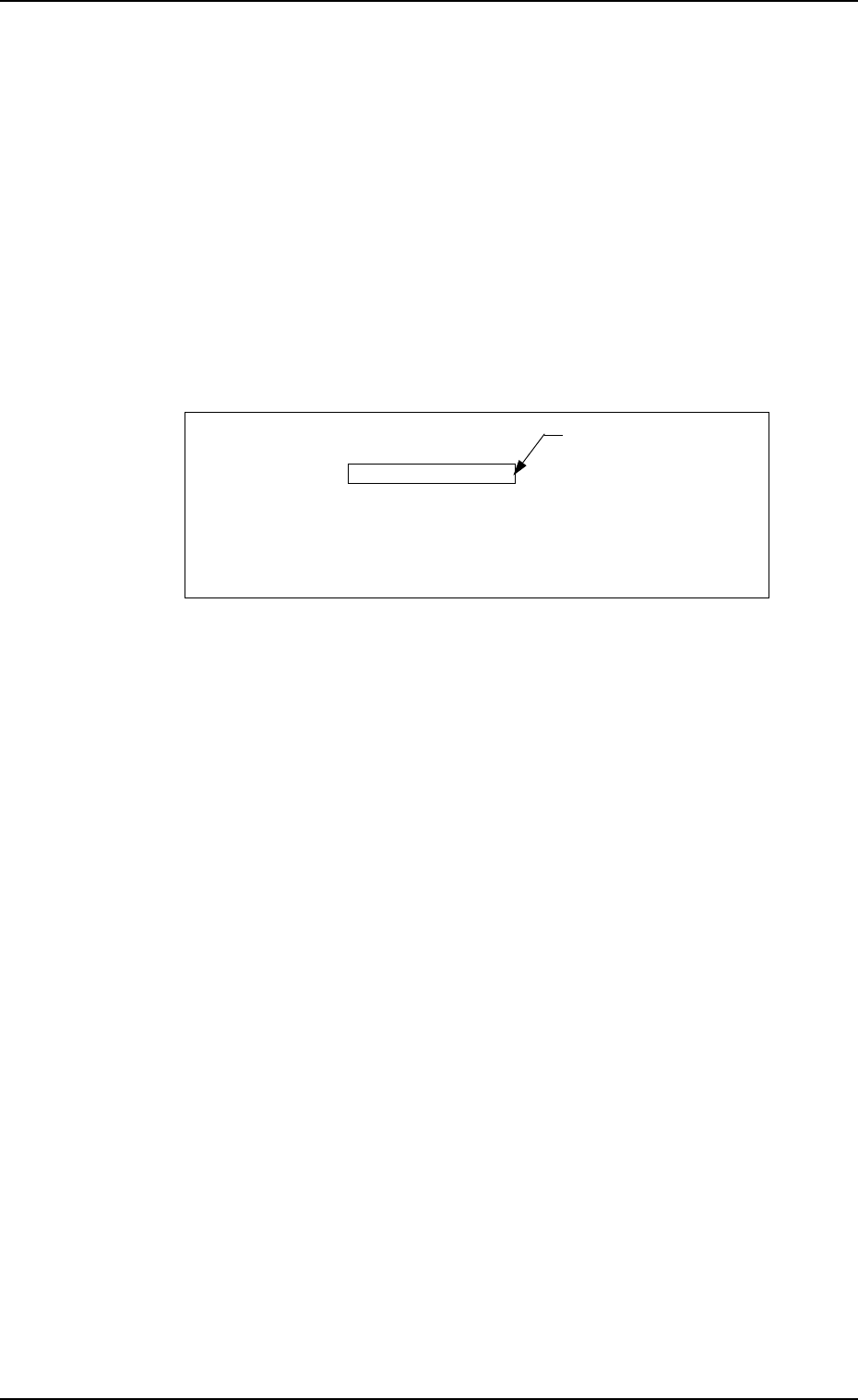
[VIBRA TOR Y STICK A] Every time the [SCREENS] key is pressed at the display (Fig. 2.32), another display appears on the screen. Fig. 2.32-2 Fig.2.32-1 Fig. 2.32 *1 [SCREENS] Key 9910-001 2-37 Tg0247-PM-PM 2. Pattern Pro…
*9 [STEP INSERT] Key
When this key is pressed, a blank lane of 1 pitch is inserted (registered) in
the feeder No. at the line cursor position.
Note: Shown below are the maximum number of units to be set for each
individual feeder.
• Tape Feeder: Max. 19
• Vibratory Stick Feeder: Max. 9
(The maximum number may decrease, depending on the stick
size.)
• Multi-Layer Tray Feeder (Option): Max. 99
Example: When the line cursor is located at FDR NO 102 at the dis-
play (Fig. 2.31-1) and this key is pressed, a blank lane is
inserted as follows.
FDR NO. COMPONENT ID
101(121) C1608T05B0 - - - 0001
102(122)
103(123) C2125T07B0 - - - 0001
104(124)
·
·
·
•
The feeder Nos. subsequent to the inserted one are shifted by 1 pitch.
*10 [STEP DELETE] Key
When the line cursor is moved to the feeder No. to be deleted and this key
is pressed, the data related to the feeder No. is deleted.
(The line at the line cursor position is deleted and the subsequent data is
shifted up.)
*11 [DATA EDIT] Key
When this key is pressed, a component data edit display opens.
A blank lane is inserted.
2. Pattern Program
9910-001 2-36 Tg0247-PM-PM
[VIBRATORY STICK A]
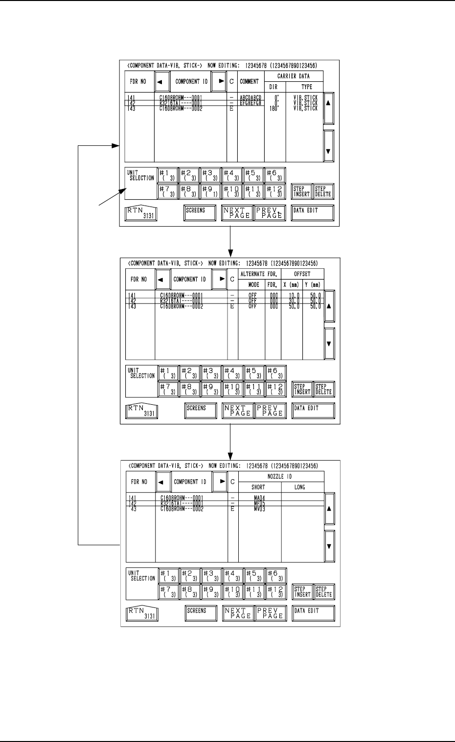
Every time the [SCREENS] key is pressed at the display (Fig. 2.32), another
display appears on the screen.
Fig. 2.32-2
Fig.2.32-1
Fig. 2.32
*1
[SCREENS] Key
9910-001 2-37 Tg0247-PM-PM
2. Pattern Program
*1 UNIT SELECTION [#1 ( X)] through [#12 ( X)] Keys
When one of these keys is pressed, the component data related to the se-
lected vibratory stick unit appears on the screen.
When parameters are set in the component data, the background color is
turned green.
The numbers in ( ) show the number of registered steps (number of feeder
Nos.)
.
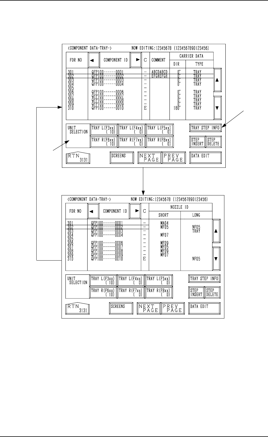
[TRAY L]
Every time the [SCREENS] key is pressed at the display (Fig. 2.33), another
display appears on the screen.
Fig. 2.33-1
*1
*2
Fig. 2.33
[SCREENS] Key
2. Pattern Program
9910-001 2-38 Tg0247-PM-PM
*1 UNIT SELECTION [TRAY L (F3xx) ( X)], [TRAY L (F4xx) ( X)],
[TRAY L (F5xx) ( X)], [TRAY R (F6xx) ( X)], [TRAY R (F7xx) ( X)],
and [TRAY R (F8xx) ( X)] Keys
It is a key which switches the display of component data to other units.
When parameters are set in the component data, the background color is
turned green.
The numbers in ( ) show the number of registered steps (number of feeder
Nos.).
*2 [TRAY STEP INFO] Key
When this key is pressed, the “TRAY (L) or (R) STEPS INFORMATION”
display appears on the screen.