2OM-1064-002.pdf - 第173页
[HEAD MASTER OFFSET] Key When this key is pressed, the “HEAD MASTER OFFSET” display appears on the screen, enabling the correction of the positional deviation (placement coordinates) caused due to the deviation of straig…
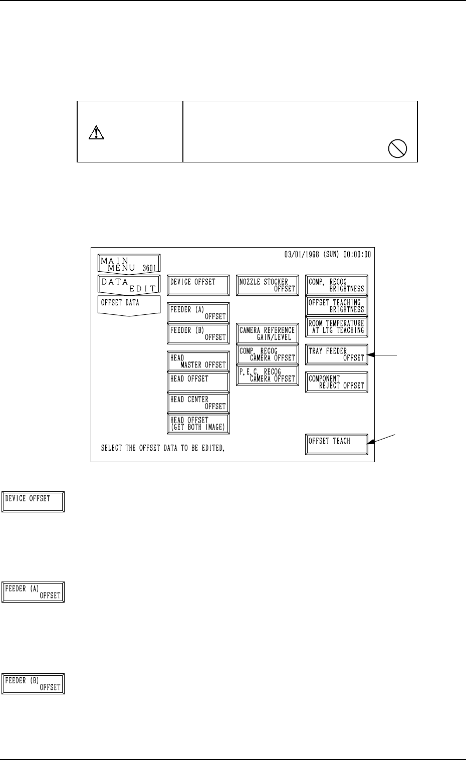
Fig. 5.1
[DEVICE OFFSET] Key
When this key is pressed, the “DEVICE OFFSET” display
appears on the screen, enabling the adjustment of the posi-
tional and angular deviations based on the design dimensions
representing the A/B beam driving X/Y coordinates viewed
from the P.C.B. positioning X/Y coordinates.
[FEEDER (A) OFFSET] Key
When this key is pressed, the “FEEDER (A) OFFSET” dis-
play appears on the screen, enabling the adjustment of the po-
sitional deviation based on the design dimensions represent-
ing the component pick-up position and height of the feeder
for each individual feeder slot Nos. (FDR. NO.).
[FEEDER (B) OFFSET] Key
When this key is pressed, the “FEEDER (B) OFFSET” dis-
play appears on the screen, enabling the correction of the varia-
tions, etc., for each individual feeders.
1. OFFSET DATA Display
This session describes how to set various kinds of offset data for each device
position adjustment related to machine operation, for the camera system re-
lated to placement accuracy, for the heads, and for the nozzles.
CAUTION
Do not change the parameters unless neces-
sary. They are factory-adjusted and set upon
shipment of the machine.
• Some parameters are automatically computed through teaching operation.
When the [OFFSET DATA] key is pressed at the “DATA EDIT” display, the
following display appears on the screen.
Note: The -marked function is optional.
1. OFFSET DATA Display
*1
9910-001 5-2 Tg0247-PM-PM
[HEAD MASTER OFFSET] Key
When this key is pressed, the “HEAD MASTER OFFSET”
display appears on the screen, enabling the correction of the
positional deviation (placement coordinates) caused due to the
deviation of straightness (skew) of each individual head up/
down axis guides.
The offset values are not reflected on the automatic teaching
operation.
[HEAD OFFSET] Key
When this key is pressed, the “HEAD OFFSET” display ap-
pears on the screen, enabling the correction of the positional
deviation (placement coordinates) caused due to the deviation
of straightness (skew) of each individual head up/down axis
guides.
[HEAD CENTER OFFSET] Key
When this key is pressed, the “HEAD CENTER OFFSET”
display appears on the screen, enabling the setting of the dis-
tance (the deviation from the design value) between the scan-
ning coordinate center of the P.E.C. camera and the head rota-
tional center.
[NOZZLE STOCKER OFFSET] Key
When this key is pressed, the “NOZZLE STOCKER OFFSET”
display appears on the screen, enabling the positional adjust-
ment of the nozzle stocker unit based on the P.C.B. position-
ing reference.
[CAMERA REFERENCE GAIN/LEVEL] Key
When this key is pressed, the “CAMERA REFERENCE GAIN
· LEVEL” display appears on the screen, showing the amplifi-
cations set at the “COMPONENT RECOG CAMERA OFF-
SET” and “P.E.C. RECOG. CAMERA OFFSET” displays.
[COMP. RECOG CAMERA OFFSET] Key
When this key is pressed, the “COMPONENT RECOG CAM-
ERA OFFSET” display appears on the screen, enabling the
adjustment of the positional and angular deviations based on
the design dimensions representing the center of the compo-
nent recognition camera viewed from the P.C.B. positioning
X/Y coordinates.
[P.E.C. RECOG CAMERA OFFSET] Key
When this key is pressed, the “P.E.C. RECOG CAMERA
OFFSET” display appears on the screen, enabling the hori-
zontal swing adjustment, etc., of the P.E.C. recognition cam-
era.
[COMP. RECOG BRIGHTNESS] Key
When this key is pressed, the “COMPONENT RECOGNI-
TION BRIGHTNESS” display appears on the screen, enabling
the brightness adjustment to obtain almost the same bright-
ness for the four head lighting devices.
1. OFFSET DATA Display
9910-001 5-3 Tg0247-PM-PM
[OFFSET TEACHING BRIGHTNESS] Key
When this key is pressed, the “OFFSET TEACHING BRIGHT-
NESS” display appears on the screen, enabling the setting of
brightness values through automatic teaching operation based
on the image captured in the lighting system for the offset teach-
ing operation.
[ROOM TEMPERATURE AT LTG TEACHING] Key
Reserved Data
[TRAY FEEDER OFFSET] Key (Option)
When this key is pressed, the “TRAY FEEDER OFFSET” dis-
play appears on the screen, enabling the adjustment of the po-
sition where a pallet is drawn out from the magazine by the
traverse shaft.
[COMPONENT REJECT OFFSET] Key
When this key is pressed, the “NG WORK STORAGE OFF-
SET” display appears on the screen, enabling the adjustment
of the positional and vertical (height direction) deviations, com-
pared with the design dimensions of the component storage
box position.
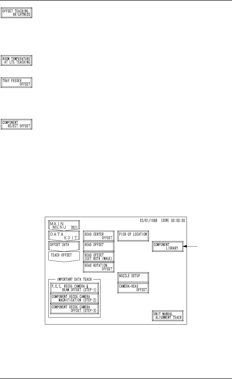
When the [OFFSET TEACH] key *1 is pressed at the “OFFSET DATA” dis-
play (Fig. 5.1), the following display appears on the screen.
This display can also be opened from the “SPECIAL SEL.” dis-
play.
Note: The -marked function is optional.
1. OFFSET DATA Display
Fig. 5.2
• Refer to “6. OFFSET TEACH Display of Section 3 in Volume 4” for de-
tails.
0004-002 5-4 Tg0247-PM-PM