2OM-1064-002.pdf - 第206页
MAGNIFICA TION 0.01µm/pixel X (Horizontal), Y (V ertical): Used commonly for each camera These parameters are used to set the magnification of the com- ponent recognition camera in the increments of 0.01 µm per pixel. Pa…
A
9910-001 5-35 Tg0247-PM-PM
9. COMPONENT RECOG CAMERA OFFSET Display
9. COMPONENT RECOG CAMERA OFFSET Display
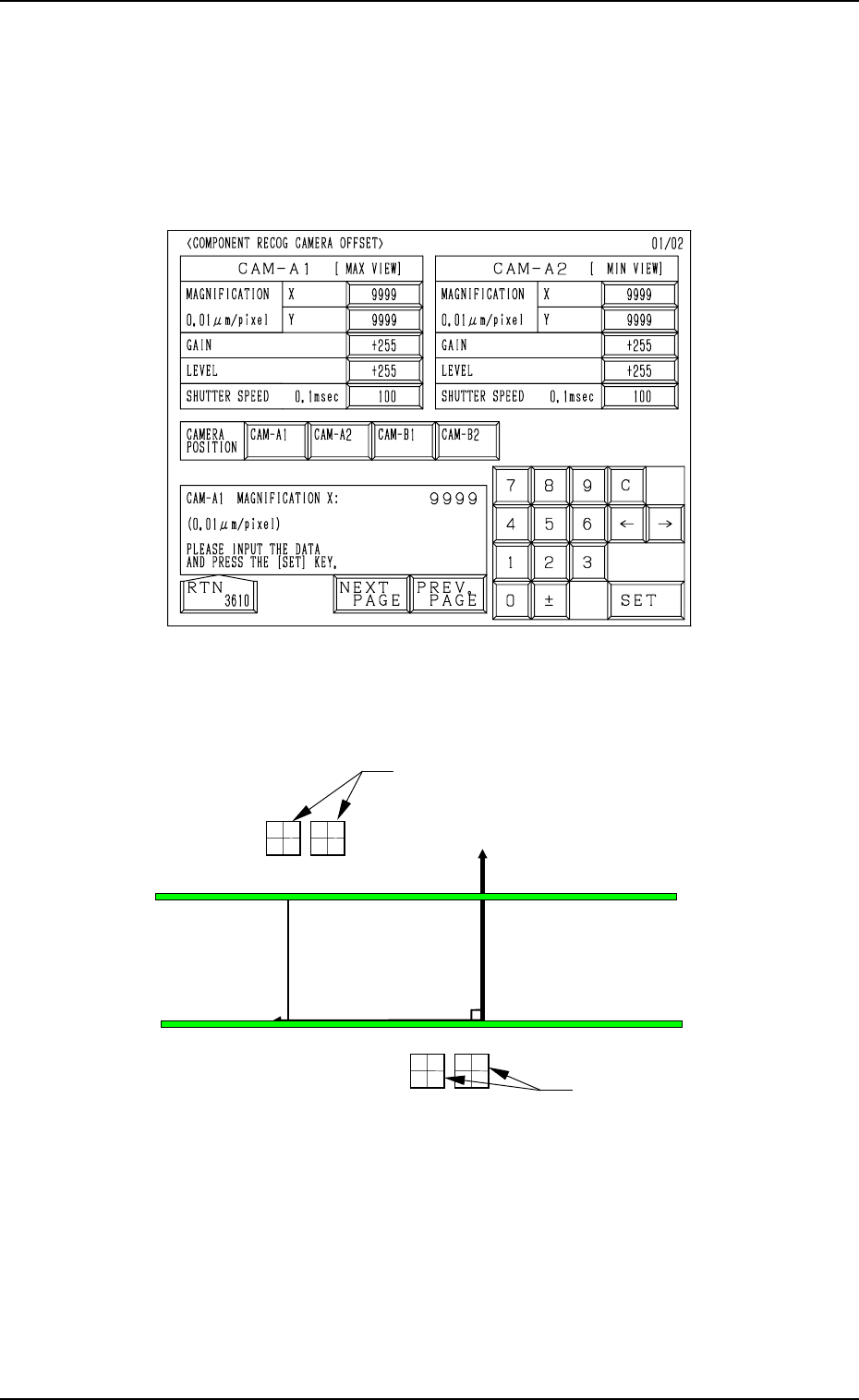
When the [COMP. RECOG CAMERA OFFSET] key is pressed at the “OFF-
SET DATA” display, the following display appears on the screen.
Every time the [NEXT PAGE] or the [PREV. PAGE] key is pressed, the next or
the previous page appears, enabling you to set parameters for different cam-
eras.
P. C.B. Positioning
X/Y Coordinates
PL-XY
PL-Y (+)
PL-X (+)
P0
CAM-B1CAM-B2
CAM-A2
CAM-A1
(Front Side of Machine)
Top View
Com
p
onent Reco
g
nition Camera
Com
p
onent Reco
g
nition Camera
Fig. 5.33
• Parameters can be entered for each individual cameras “CAM-A1”, “CAM-
A2”, “CAM-B1”, and “CAM-B2”.
Fig. 5.34
MAGNIFICATION 0.01µm/pixel X (Horizontal), Y (Vertical):
Used commonly for each camera
These parameters are used to set the magnification of the com-
ponent recognition camera in the increments of 0.01 µm per
pixel.
Parameters must be entered for both X and Y directions.
This offset data is automatically calculated through teaching
operation which is performed, using a jig component for mag-
nification measurement.
GAIN/LEVEL: Used commonly for each camera
These parameters are used to set amplifications at which the
signals of the image taken by the component recognition cam-
era is converted into the picture information representing bright-
ness.
Parameters are set as the offset values for camera reference
gain and level.
Normal Fixed Value: ±0
• The lower the gain is, the bigger the contrast becomes.
• The lower the level is, the brighter the whole view becomes.
SHUTTER SPEED 0.1msec
The set parameter represents the exposure time of the camera.
Up to 110 (= 11 ms) can be set in the case of the component
recognition camera.
Set parameters such that the same brightness is obtained for
“CAM-A1”, “CAM-A2”, “CAM-B1”, and “CAM-B2”.
• The bigger the value (shutter speed data) is, the longer the ex-
posure time becomes, making the captured image brighter.
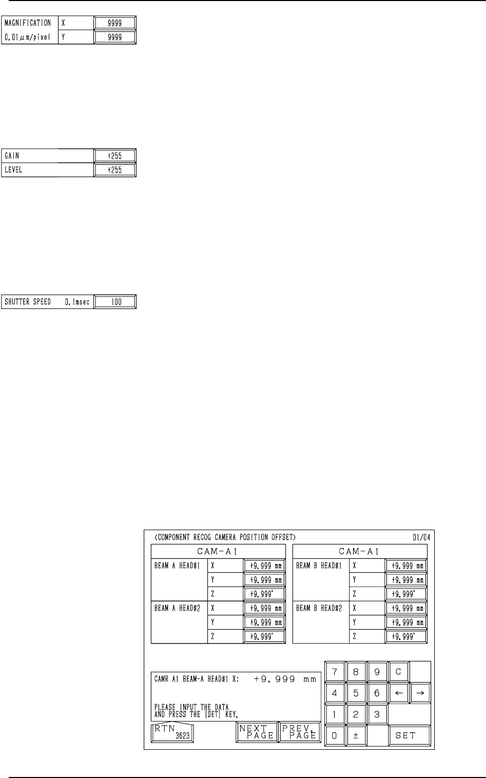
When the [CAM-A1], the [CAM-A2], the [CAM-B1], or the
[CAM-B2] key (CAMERA POSITION) is pressed at the “COM-
PONENT RECOG CAMERA OFFSET” display, the following
display appears on the screen.
Every time the [NEXT PAGE] or the [PREV. PAGE] key is
pressed, the next or the previous page appears, enabling you to
set parameters for different cameras.
9. COMPONENT RECOG CAMERA OFFSET Display
Fig. 5.35
9910-001 5-36 Tg0247-PM-PM
Common Items on Pages 1 to 4
BEAM A HEAD#1 X (Horizontal), Y (Vertical), Z (Angle):
Used commonly for each camera
The set offset data is used to adjust the positional and angular
deviations based on the design dimensions representing the
center (scanning coordinate center) of the component recog-
nition camera viewed from the P.C.B. positioning X/Y coordi-
nates (PL-XY: Origin P0). The values based on the PL-XY
coordinate system must be entered in the data boxes.
When the teaching operation is performed, the values calcu-
lated automatically using Head #1 on Beam A are saved and
used to figure out the placement correction values for Head #1
on Beam A.
• Design Values
CAM-A1
X: + 425.000 mm, Y: +496.000 mm
CAM-A2
X: + 317.000 mm, Y: +496.000 mm
CAM-B1
X: + 35.000 mm, Y: -130.000 mm
CAM-B2
X: + 143.000 mm, Y: -130.000 mm
When the camera scanning coordinate system deviates coun-
terclockwise from the P.C.B. positioning X/Y coordinate (PL-
XY) system, a plus value must be entered as “Z” (camera angle).
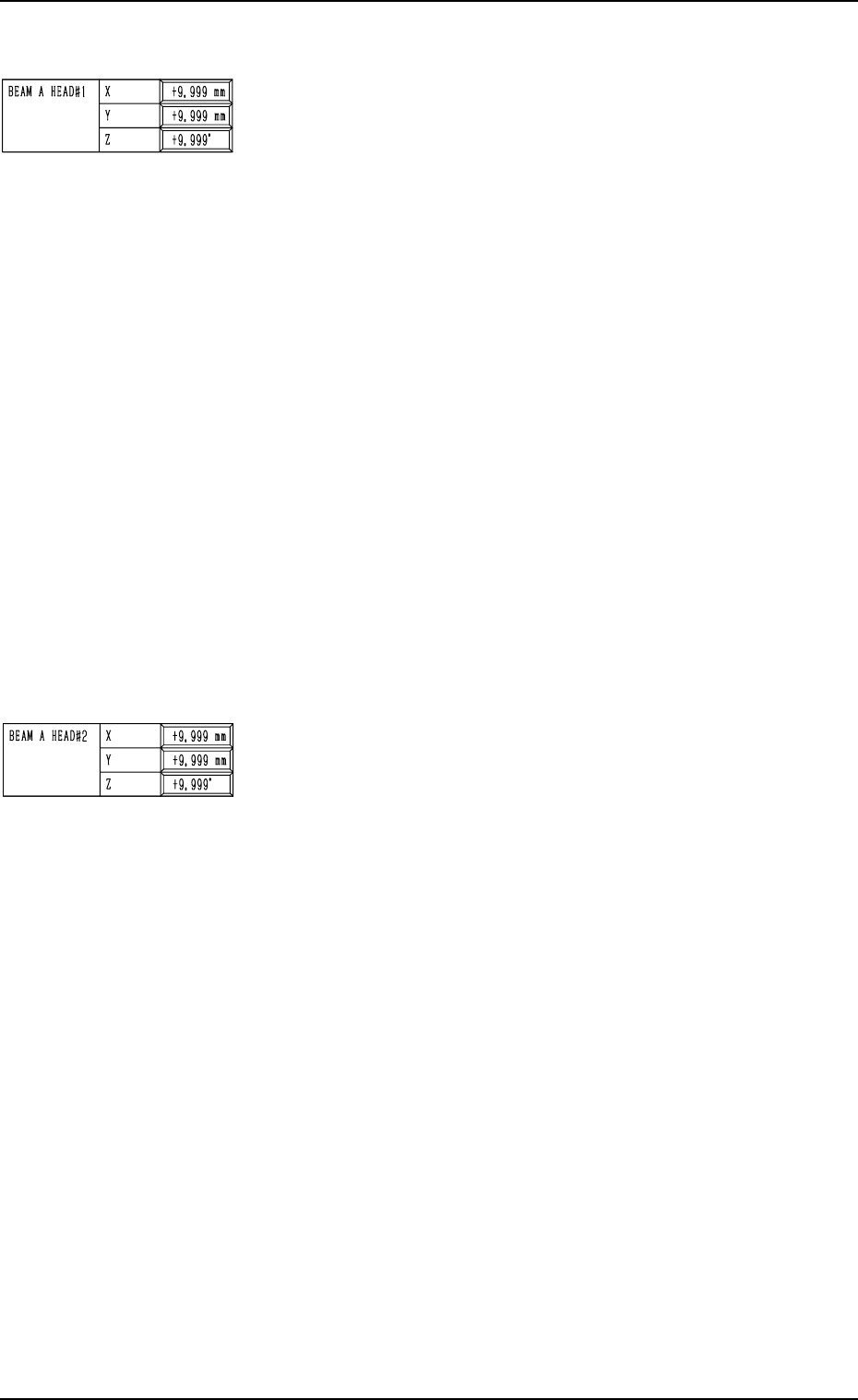
BEAM A HEAD#2 X (Horizontal), Y (Vertical), Z (Angle):
Used commonly for each camera
The set offset data is used to adjust the positional and angular
deviations based on the design dimensions representing the
center (scanning coordinate center) of the component recog-
nition camera viewed from the P.C.B. positioning X/Y coordi-
nates (PL-XY: Origin P0). The values based on the PL-XY
coordinate system must be entered in the data boxes.
When the teaching operation is performed, the values calcu-
lated automatically using Head #2 on Beam A are saved and
used to figure out the placement correction values for Head #2
on Beam A.
• Design Values
CAM-A1
X: + 425.000 mm, Y: +496.000 mm
CAM-A2
X: + 317.000 mm, Y: +496.000 mm
CAM-B1
X: + 35.000 mm, Y: -130.000 mm
CAM-B2
X: + 143.000 mm, Y: 130.000 mm
When the camera scanning coordinate system deviates coun-
terclockwise from the P.C.B. positioning X/Y coordinate
(PL-XY) system, a plus value must be entered as “Z” (cam-
era angle).
9. COMPONENT RECOG CAMERA OFFSET Display
9910-001 5-37 Tg0247-PM-PM