2OM-1064-002.pdf - 第59页
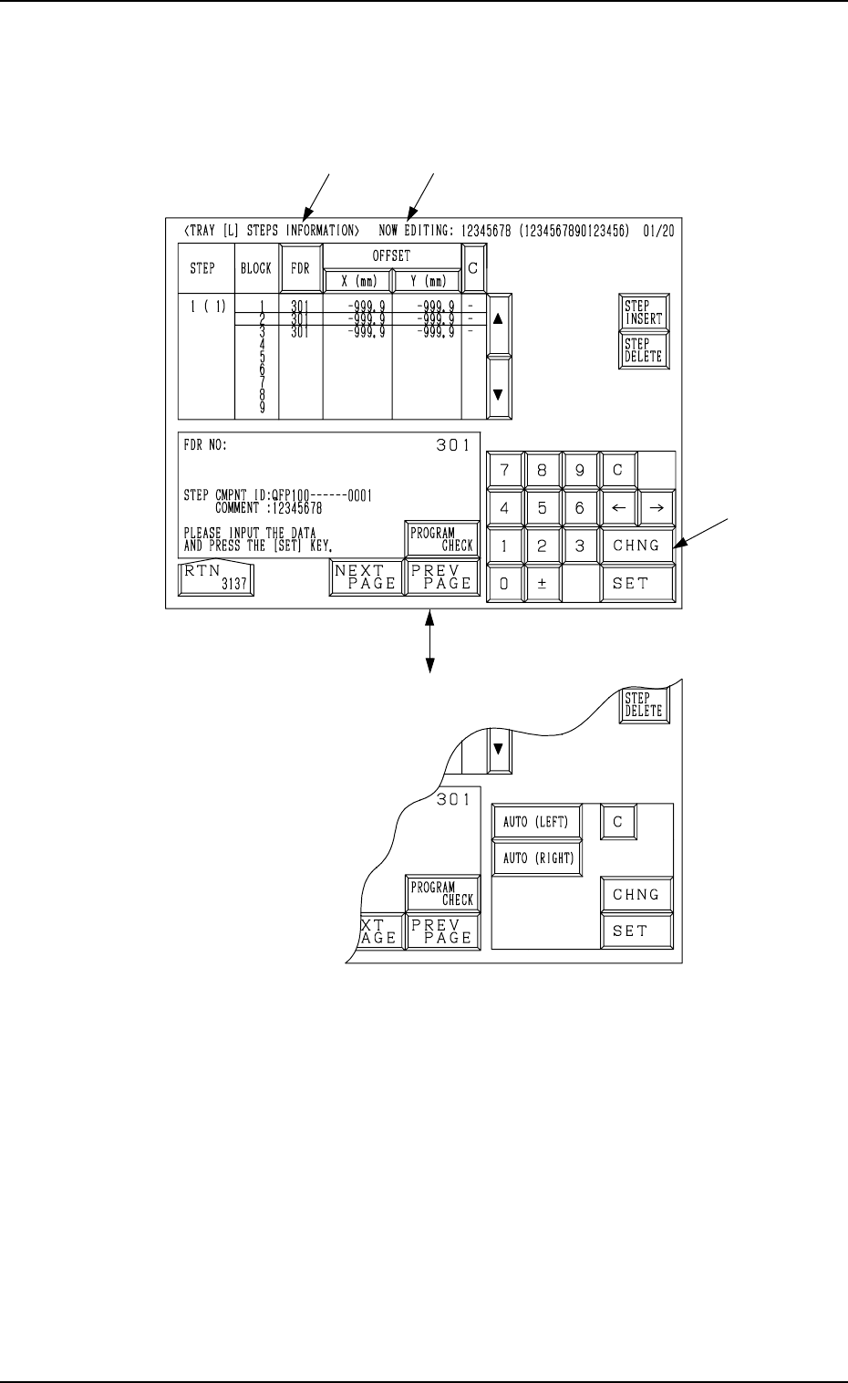
*1 *2 Fig. 2.39-1 Fig. 2.39-2 [CHNG] Key A 0004-002 2-47 Tg0247-PM-PM When the [1 ( 1)] key is pressed at the display for “TRA Y L” (Fig. 2.38) , the following display appears on the screen. Note: The [CHNG] key A appear…

9910-001 2-46 Tg0247-PM-PM
Carriage Alternate Function
The trays having the same type of components can be set on several stages
(pallets) in the magazines. Every time the machine gets empty of compo-
nents, it automatically selects another spare stage which stores the tray hav-
ing the same type of components, making it possible for the machine to
perform the operation continuously.
By providing several stages with a group of components used frequently
among the component types, an interval of component supply can be pro-
longed.
The order of the carriage alternate actions is based on the ascending order
(advancing from a smaller step No.) of the magazine step Nos.
Example: To take out “FDR No. 301” in Fig. 2.38
(1,1) → (1,2) → (1,3) → (2,1) → (3,1) . . .
2. Pattern Program
Step
Block No.
*1
*2
Fig. 2.39-1
Fig. 2.39-2
[CHNG] Key
A
0004-002 2-47 Tg0247-PM-PM
When the [1 ( 1)] key is pressed at the display for “TRAY L” (Fig. 2.38) , the
following display appears on the screen.
Note: The [CHNG] key A appears only when the [X (mm)] key under “OFF-
SET” is selected.
2. Pattern Program
9910-001 2-48 Tg0247-PM-PM
*1 [FDR] Key
Set the type of components (FDR NO) for each individual step Nos. and
blocks.
*2 OFFSET X (mm), Y (mm)
Set the coordinates of the tray origin corner to be positioned when a tray is
set in the pallet. The coordinates must be determined based on the pallet
reference position.
Note: The coordinates to be entered as positional offset are based on the
reference mark and fixed regardless of whether Tray L or R is used.
• When several trays are put on one pallet (when several blocks are used),
it is required to set positional offsets (X and Y) for each individual blocks.
By specifying the tray origin corner position, the pick-up position of
each tray is automatically calculated based on the component library data.
(“SIDE”, “PITCH”, “MATRIX”, etc.)
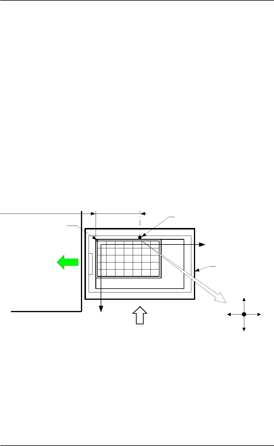
Case: Tray L
It is recommended that the tray should be set as shown in Fig. 2.40-1 to
ensure the X/Y-beam movable range as wide as possible. In this case, select
the [AUTO (LEFT)] key.
• When one tray is set on one pallet and brought to the left side, the posi-
tional offset (X, Y) is fixed as “X = -182.5 mm” and “Y = +0.0 mm”.
2. Pattern Program
Pallet Drawing Direction
Magazine
Main Body of Machine
Pallet Supply Direction
Reference Mark (Rivet)
Tray Origin Corner
Matrix Y Direction
Matrix X Direction
Positional Offset X: -182.5 mm (Fixed)
X (+)X (-)
Y (-)
Y (+)
Beam A Side
Fig. 2.40-1