2OM-1064-002.pdf - 第19页
*4 *3 *6 *5 *1 *2 2. Pattern Program 0004-002 2-7 Tg0247-PM-PM Fig. 2.4 *1 NOZZLE ID The nozzle IDs used in the selected pattern program are displayed. *2 NUM The number of each nozzle (nozzles in the “NOZZLE ID” data fi…
*2
*1
2. Pattern Program
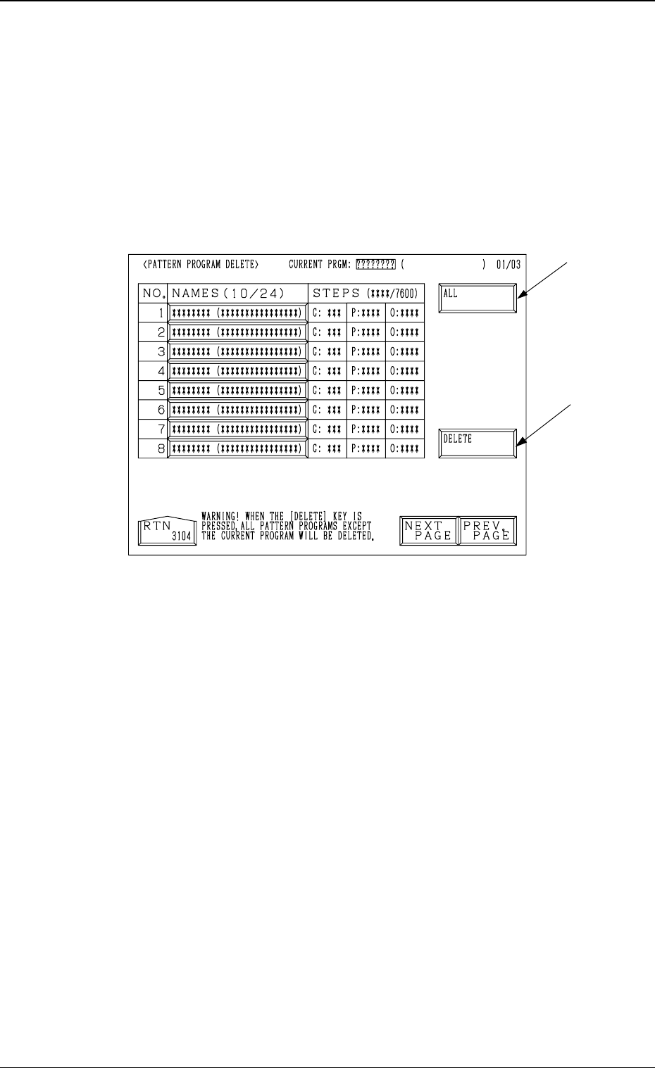
2.1.2 PATTERN PROGRAM DELETE Display
When the “NAME (XX/XX)” key of the program data to be deleted is selected
and the [PROGRAM DELETE] key is pressed at the “PATTERN PROGRAM”
display (Fig. 2.1), the following display appears on the screen.
• The pattern program is deleted.
• Use this function when the backup pattern program data is corrupted due to
the battery shortage, etc.
Refer to “4.9 Remedial Operation for Error Pattern Program Data of Section
2” for details.
9910-001 2-6 Tg0247-PM-PM
Fig. 2.3
*1 [DELETE] Key
When this key is pressed, the selected program is deleted.
*2 [ALL] Key
When this key is pressed, all programs are deleted.
*4
*3
*6
*5
*1 *2
2. Pattern Program
0004-002 2-7 Tg0247-PM-PM
Fig. 2.4
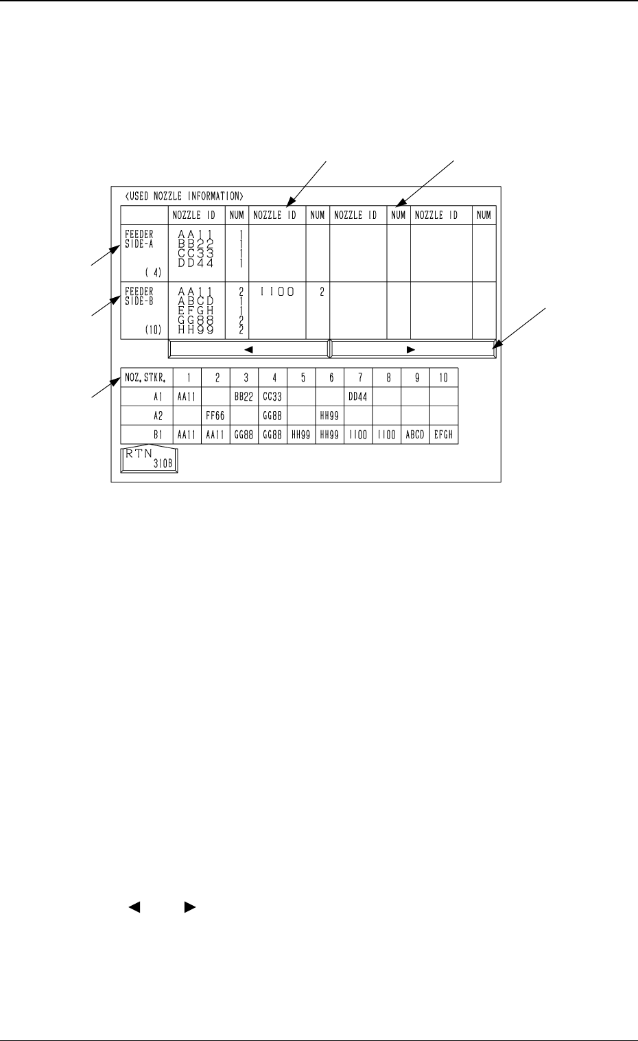
*1 NOZZLE ID
The nozzle IDs used in the selected pattern program are displayed.
*2 NUM
The number of each nozzle (nozzles in the “NOZZLE ID” data field) used
in the selected pattern program is displayed.
When the simultaneous pick-up operation is to be performed, “2” appears
in the “NOZZLE ID” data field. In the simultaneous pick-up operation,
components are picked up simultaneously by the same types of nozzles on
the two heads on the same beam.
*3 FEEDER SIDE-A
Using the selected pattern program, shown are the nozzles required to pick
up components from the feeders on Beam A Side (rear side).
*4 FEEDER SIDE-B
Using the selected pattern program, shown are the nozzles required to pick
up components from the feeders on Beam B Side (front side).
*5 [ ] and [ ] Keys
Click this to pull the data fields horizontally into view.
The data fields (“NOZZLE ID” and “NUM” fields) are scrolled horizon-
tally.
2.1.3 USED NOZZLE INFORMATION Display
• The nozzle IDs to be used in the selected pattern program and whether or
not the nozzles are set in the stockers can be checked.
When the [USED NOZZLE INFORMATION] key is pressed at the “PATTERN
PROGRAM” display, the following display appears on the screen.
*6 NOZ. STKR.
The conditions of the nozzles actually set in the nozzle stockers can be
checked.
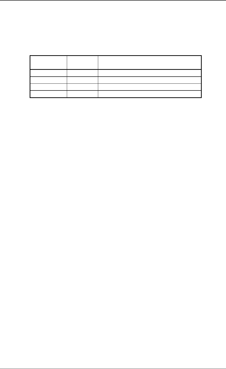
Colour code (coloured nozzle IDs) are used to indicate the nozzles use con-
ditions as shown in the following table.
Table 2.1
2. Pattern Program
Character Color
Background
Color
Condition
Green Black Used in Selected Pattern Program
White Black Not Used in Selected Pattern Program
None Red Bypassed Nozzle Stocker Address
No Indication None Nozzle Stocker Empty
0004-002 2-8 Tg0247-PM-PM