2OM-1064-002.pdf - 第85页
9910-001 2-73 Tg0247-PM-PM Parameters are based on the reference point “L-BACK”. They change depending on where the reference point is specified. Fig. 2.51 Examples of Component Placement Based on Difference in Reference…

3. Example of Pattern Program Creation
Placement Data (P-No. Data: U01)
O-NO X
(mm)
Y
(mm)
Z=THETA
H (mm) C COMMENT
0000
+00.00 +00.00 +00
°
00’ +0.00 -
0001
000.00 000.00 000
°
00’ +0.00 -
0002
080.00 000.00 000
°
00’ +0.00 -
0003
080.00 080.00 000
°
00’ +0.00 -
0004
000.00 080.00 000
°
00’ +0.00 -
0005
000.00 000.00 000
°
00’ +0.00 E
P-No. X
(mm)
Y
(mm)
Z=THETA
H (mm) FDR S V C COMMENT COMPONENT ID
0000
+00.00 +00.00 +00
°
00’ +0.00 000
-
00 -
0001
020.00 025.00 090
°
00’ +0.00 601 2 00 - QFP100-B00SAN-T
0002
055.00 025.00 000
°
00’ +0.00 301
-
00 - BGA225-B00SAN-T
0003
015.00 050.00 000
°
00’ +0.00 101 1 00 - R3216T06B0---
0004
025.00 050.00 000
°
00’ +0.00 107
-
00 - TR2915-3B0SAN-L2
0005
055.00 050.00 000
°
00’ +0.00 101 1 00 - R3216T06B0---
0006
065.00 050.00 000
°
00’ +0.00 107
-
00 - TR2915-3B0SAN-L2
0007
035.00 050.00 000
°
00’ +0.00 201 2 00 - MPTR4525B0SAN-L3
0008
045.00 050.00 090
°
00’ +0.00 210
-
00 - SOP014-B00SAN83A
0009
010.00 060.00 000
°
00’ +0.00 201 2 00 - MPTR4525B0SAN-L3
0010
022.00 060.00 090
°
00’ +0.00 210
-
00 - SOP014-B00SAN83A
0011
034.00 060.00 000
°
00’ +0.00 201 2 00 - MPTR4525B0SAN-L3
0012
046.00 060.00 090
°
00’ +0.00 210
-
00 - SOP014-B00SAN83A
0013
058.00 060.00 000
°
00’ +0.00 201 2 00 - MPTR4525B0SAN-L3
0014
070.00 060.00 090
°
00’ +0.00 210
-
00 - SOP014-B00SAN83A
0015
000.00 000.00 000
°
00’ +0.00 000
-
00 P
Placement Data (O-No. Data: U01)
9910-001 2-72 Tg0247-PM-PM
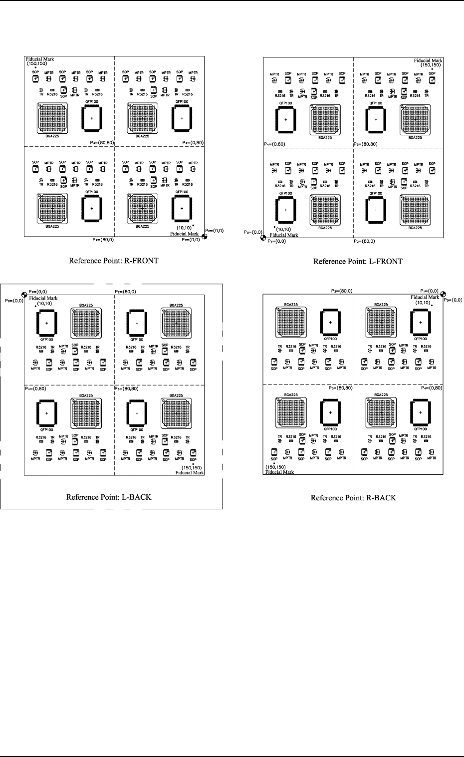
9910-001 2-73 Tg0247-PM-PM
Parameters are based on the reference point “L-BACK”.
They change depending on where the reference point is specified.
Fig. 2.51 Examples of Component Placement Based on Difference in Reference Points
3. Example of Pattern Program Creation
3.2 Example 2 (Example of Placement Data Creation)
3.2.1 Normal Placement Data
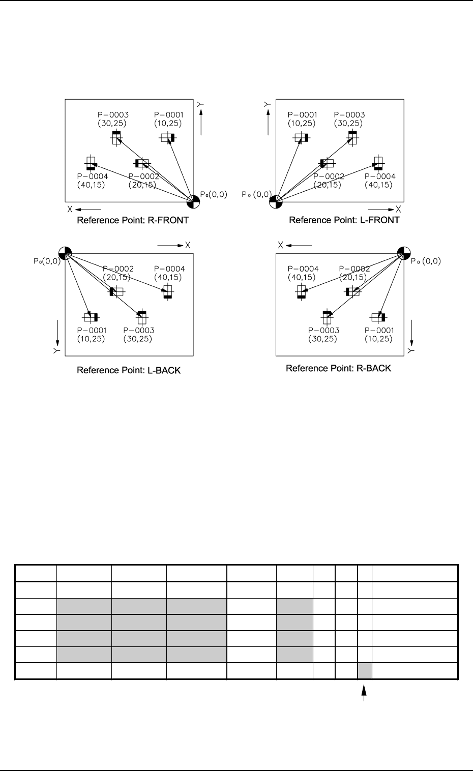
(1) Pattern Sample
• The figure below shows an example of placing four components on the
P.C.B.
3. Example of Pattern Program Creation
Fig. 2.52
Notes: (a) P
0
shows the P.C.B. positioning reference.
(b) The placement coordinates of a component are measured based
on the P.C.B. positioning reference (0, 0).
(2) Example of Data Creation
• Use placement data (P) U01.
• Do not enter any parameters in placement data (O) because it is not
used.
When it is not necessary to perform any P.E.C. recognition on each
individual components, do not set any parameters as placement data
(V).
PLACEMENT DATA (P) U01
Enter “0” (zero) in all data fields of the last step and “E” as
a control command.
(Component placement is not implemented for the step where a
control command other than “-” and “D” is entered.)
Fig. 2.53
P-NO. X(mm) Y(mm) Z(THETA) H(mm) FDR S V C COMMENT
0000 +0.00 +0.00 +0
°
00’ +0.00 000 - 00 -
0001 +10.00 +25.00 +0
°
00’ +0.00 101 - 00 -
0002 +20.00 +15.00 +180
°
00’ +0.00 201 - 00 -
0003 +30.00 +25.00 +90
°
00’ +0.00 301 - 00 -
0004 +40.00 +15.00 +270
°
00’ +0.00 601 - 00 -
0005 +0.00 +0.00 +0
°
00’ +0.00 000 - 00 E
9910-001 2-74 Tg0247-PM-PM