2OM-1064-002.pdf - 第183页
Note: The center of the mark is the reference point. 9910-001 5-13 Tg0247-PM-PM 3. FEEDER (A) OFFSET and FEEDER (B) OFFSET Displays X (+) Y (+) P.C.B. Rear Feeder User Direction of Tape Feed User Direction of Tape Feed F…
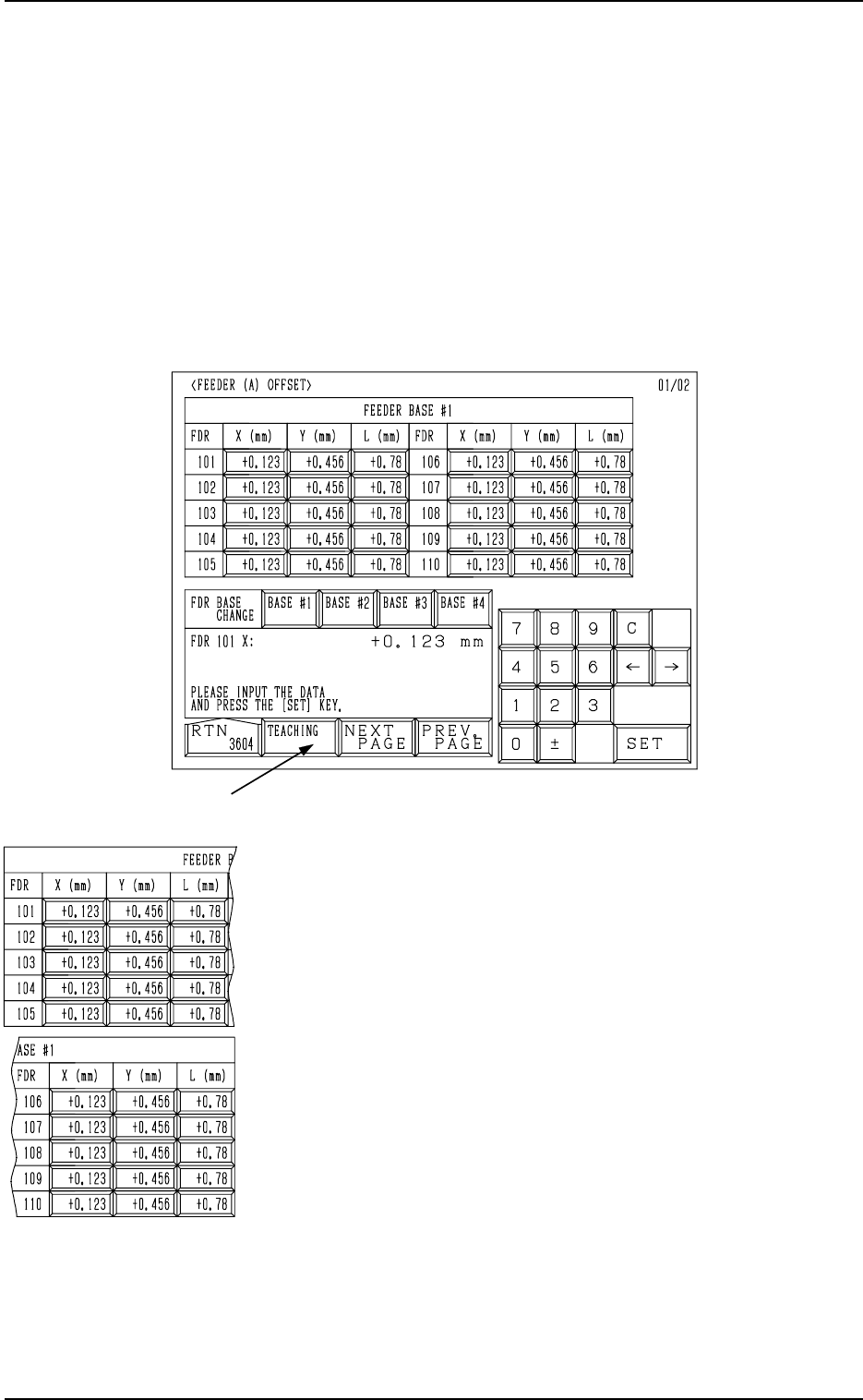
Fig. 5.10
FEEDER (A) OFFSET X (mm) and Y (mm)
The feeder (A) offset data is used to adjust the positional de-
viation based on the design dimensions representing the com-
ponent pick-up position for each individual feeder slot Nos.
(FDR. NO.).
The values based on the PL-XY coordinate system must be
entered in the data boxes.
These parameters must be measured, using the master jig and
set as the data for positional alignment with each feeder’s com-
ponent pick-up position.
Ref.: The manual alignment teaching operation is possible.
*1
3. FEEDER (A) OFFSET and FEEDER (B) OFFSET Displays
3. FEEDER (A) OFFSET and FEEDER (B) OFFSET
Displays
• The feeder (A) offset data is used independently for the machine and repre-
sents the feeder’s component pick-up position indicated by each individual
feeder slot Nos. (FDR. NO.).
• The feeder (B) offset data is used to correct the variation in each feeder to be
installed.
When the [FEEDER (A) OFFSET] key is pressed at the “OFFSET DATA”
display, the following display appears on the screen.
9910-001 5-12 Tg0247-PM-PM
Note: The center of the mark is the reference point.
9910-001 5-13 Tg0247-PM-PM
3. FEEDER (A) OFFSET and FEEDER (B) OFFSET Displays
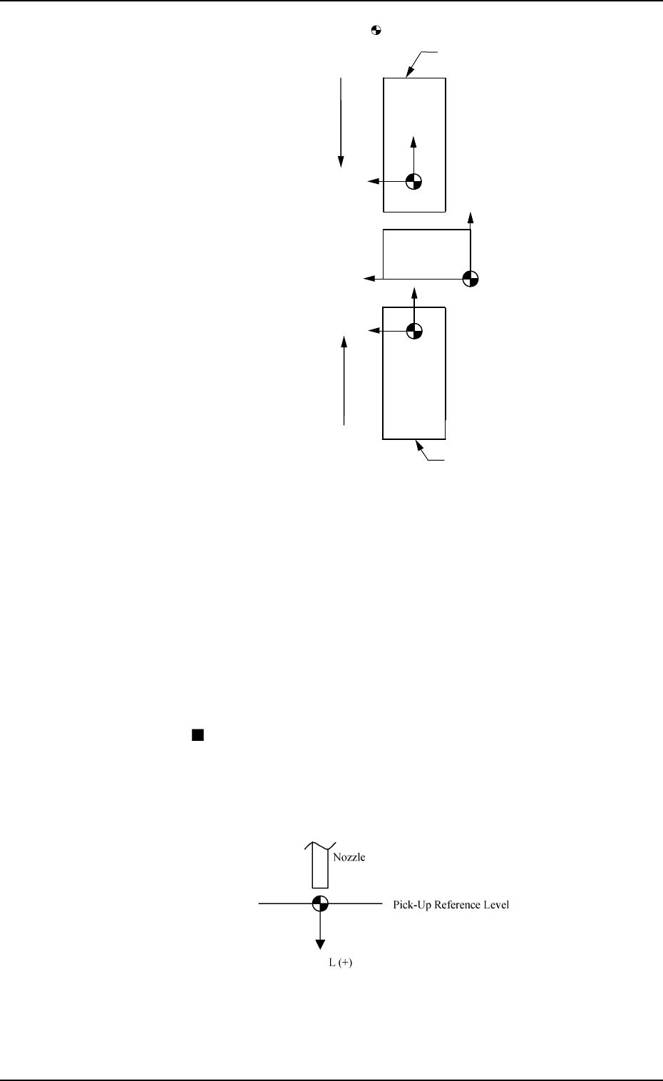
X (+)
Y (+)
P.C.B.
Rear Feeder
User Direction of Tape Feed
User Direction of Tape Feed
Front Feeder
Fig. 5.11
When offset parameters are set with a plus (+) sign, the com-
ponent pick-up directions (position) are changed to “X (+)”
and “Y (+)” shown in the above figure.
Note: Both rear (Slot Nos. 101 to 139) and front (Slot Nos.
201 to 239) feeders are not based on the feeders them-
selves. They are based on the coordinate system of the
machine.
Ref.: When the [TEACHING] key *1 is pressed, the “UNIT
MANUAL ALIGNMENT TEACH” display appears
on the screen.
Refer to “6.8.2 Feeder (A) Offset of Section 3 in Volume
4” for details.
FEEDER (A) OFFSET L (mm)
The set parameters are used to adjust the deviation of the
feeder’s component pick-up height based on the design dimen-
sions for each individual feeder slot Nos. (FDR. NO.).
These parameters are reflected on the descending stroke of the
head required to pick up a component.
Fig. 5.12
When a value is entered with a plus (+) sign, the pick-up height
is changed to “L (+)” shown in the figure above, concluding
that the descending stroke has increased.
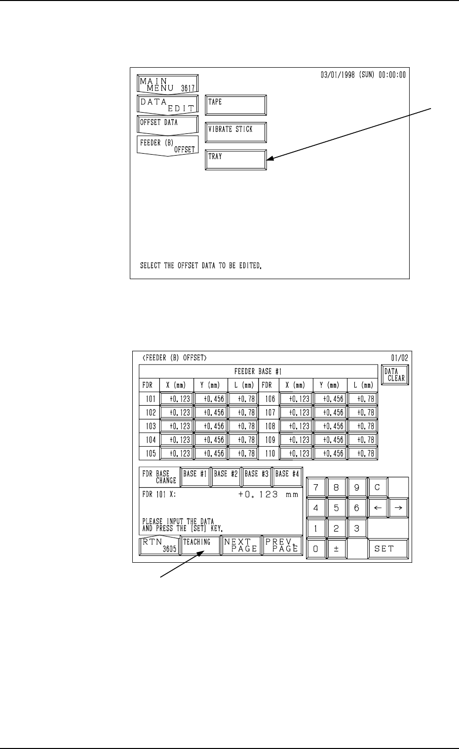
Fig. 5.14
*1
3. FEEDER (A) OFFSET and FEEDER (B) OFFSET Displays
When the [FEEDER (B) OFFSET] key is pressed at the “OFF-
SET DATA” display, the following display appears on the screen.
Note: The -marked function is optional.
9910-001 5-14 Tg0247-PM-PM
Fig. 5.13
When the [TAPE] key is selected, the following display appears
on the screen.