2OM-1064-002.pdf - 第164页
1. AUTO OPERA TION SET-UP Display *1 *2 *3 9910-001 4-2 Tg0247-PM-PM 1. AUT O OPERA TION SET-UP Display V arious parameters related to automatic operation of the machine can be set at this display . Machine performance, …

Section 4
Automatic Operation Set-Up
9910-001 4-1 Tg0247-PM-PM
1. AUTO OPERATION SET-UP Display
*1
*2
*3
9910-001 4-2 Tg0247-PM-PM
1. AUTO OPERATION SET-UP Display
Various parameters related to automatic operation of the machine can be set at
this display. Machine performance, production rate, production guidance, etc.,
can be set.
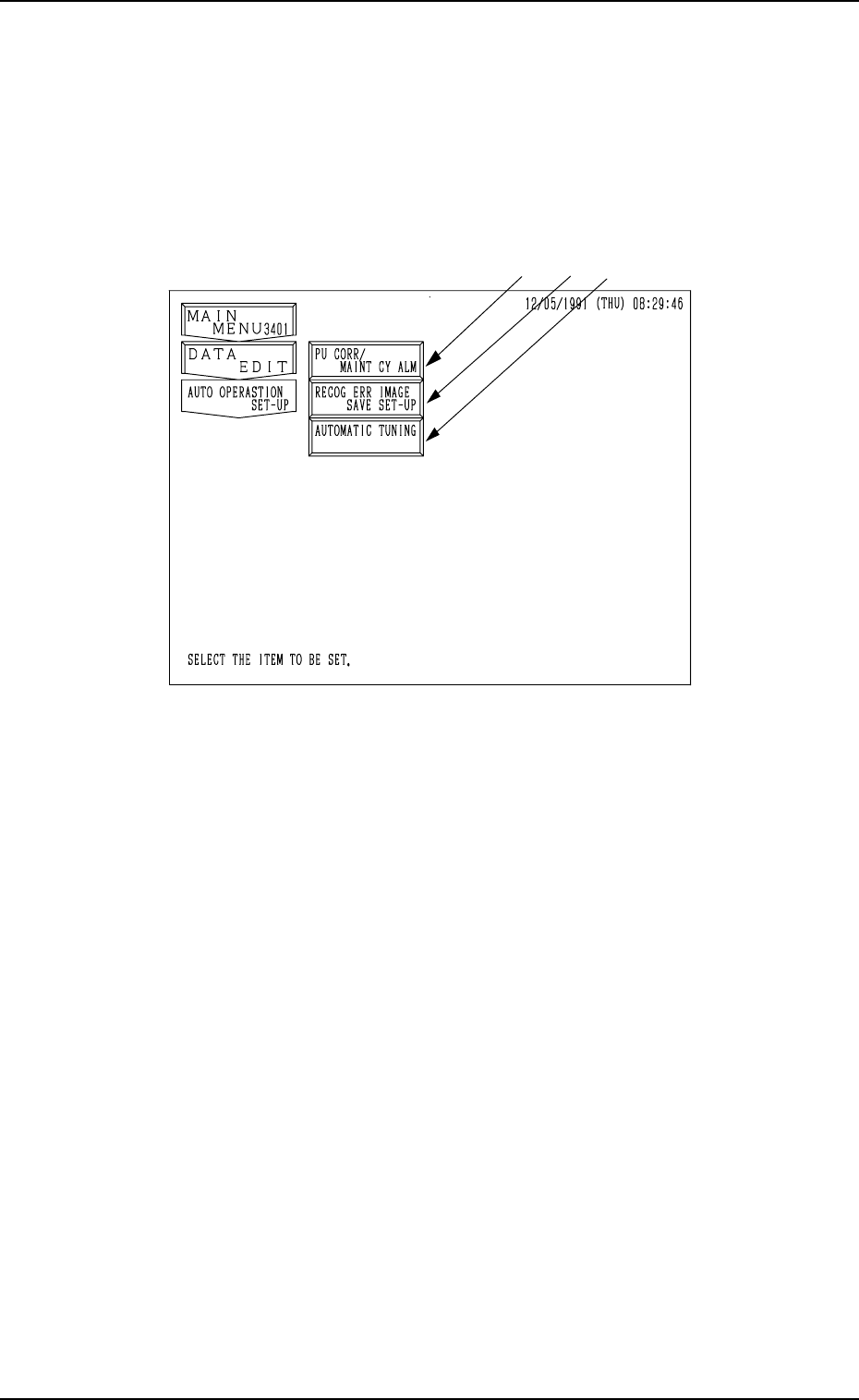
When the [AUTO OPERATION SET-UP] key is pressed at the “DATA EDIT”
display, the following display appears on the screen.
Fig. 4.1
*1 [PU CORR/MAINT CY ALM] Key
When this key is pressed, the “PICK-UP CORRECTION/MAINTENANCE
CYCLE ALARM” display opens, enabling the sensitivity setting for pick-
up correction, the setting of various guidance, and the setting of alarm indi-
cation.
*2 [RECOG ERR IMAGE SAVE SET-UP] Key
When this key is pressed, the “RECOGNITION ERROR IMAGE SAVE
SET-UP” display opens, enabling the setting for image data saving at a
recognition error.
The data can be used to analyze the cause of an error in comparison with
the error image on the monitor.
*3 [AUTOMATIC TUNING] Key
When this key is pressed, the “AUTOMATIC TUNING” display opens,
enabling the setting of timing to correct the position of each section.
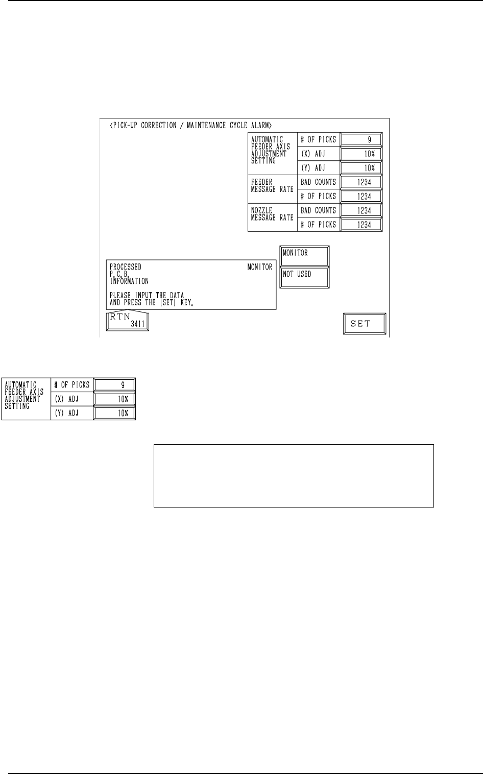
Fig. 4.2
AUTOMATIC FEEDER AXIS ADJUSTMENT SETTING
# OF PICKS, (X) ADJ, and (Y) ADJ
Set the sensitivity parameters which follow up the data learned
by using the statistical method in “FEEDER (B) OFFSET”.
New “FEEDER (B) OFFSET” = Old “FEEDER (B) OFF-
SET” + (mean of deviation
obtained n times) * Coeffi-
cient
# OF PICKS
Set the total number of collected samples when data is up-
dated or changed.
• Data Input Range: 1 to 9 (Standard Value: 3)
(X) ADJ
Set the feedback coefficient of the mean of the feeder axis’ X-
direction deviation.
• Data Input Range: 10 to 100% (Standard Value: 50%)
(Y) ADJ
Set the feedback coefficient of the mean of the feeder axis’ Y-
direction deviation.
• Data Input Range: 10 to 100% (Standard Value: 50%)
2. PICK-UP CORRECTION/MAINTENANCE CYCLE ALARM Display
2. PICK-UP CORRECTION/MAINTENANCE CYCLE
ALARM Display
When the [PU CORR/MAINT CY ALM] key is pressed at the “AUTO OP-
ERATION SET-UP” display, the following display appears on the screen.
9910-001 4-3 Tg0247-PM-PM