2OM-1064-002.pdf - 第27页
P .C.B. HEIGHT OFFSET When a P .C.B. on a jig P .C.B. (such as a mother board) is positioned, the upper surface level of the P .C.B. may extend beyond the reference plane. In this case, set the offset data. The head can …
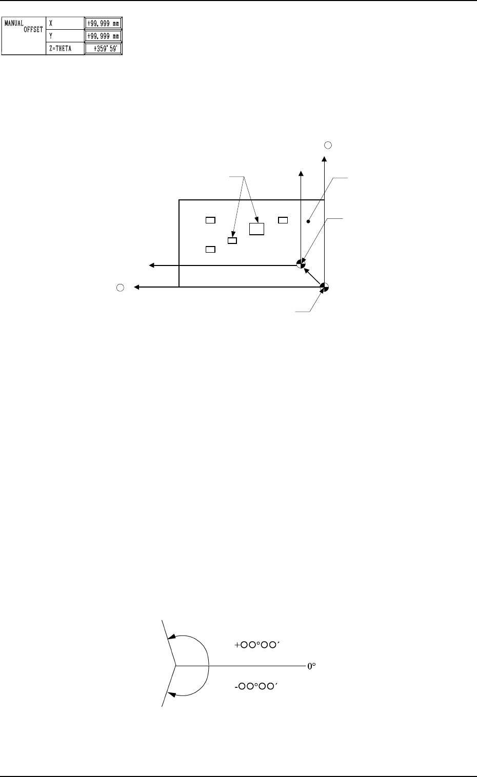
MANUAL OFFSET
X (Horizontal), Y (Vertical)
Set parameters (offset data) in the data boxes. The set param-
eters are used as offset data to correct the difference (x, y)
between the reference point (X and Y in the placement data
used to indicate the placement position) in the coordinate sys-
tem and the reference point for machine positioning based on
P.C.B. positioning to be set up when a P.C.B. is positioned.
2. Pattern Program
Fig. 2.8
The set parameters represent the values indicating the refer-
ence point in the coordinate system (placement data) based on
the reference point for machine positioning to be set up when
a P.C.B. is positioned. When a P.C.B. shown above is used,
parameters must be entered with a plus (+) sign for both X and
Y.
•
Data Input Range
X : -99.99 to +99.99 mm
Y : -99.99 to +99.99 mm
Z=THETA
Set a parameter (offset value for the angle of the component to
be placed) in the data box.
The set parameter is added commonly to the placement angle
data (Z data in the placement P data) for each individual com-
ponent to be placed.
To correct the angle of component placement counterclock-
wise, a parameter must be entered with a plus (+) sign. A mi-
Components
Y +
Coordinate Reference
for Placement Data
Reference Point for Machine Positioning: “Outline” Reference
P.C.B.
X +
nus (-) sign must be affixed for clockwise correction.
Plane View
Fig. 2.9
• Data Input Range: -359°59´ to +359°59´
0004-002 2-14 Tg0247-PM-PM
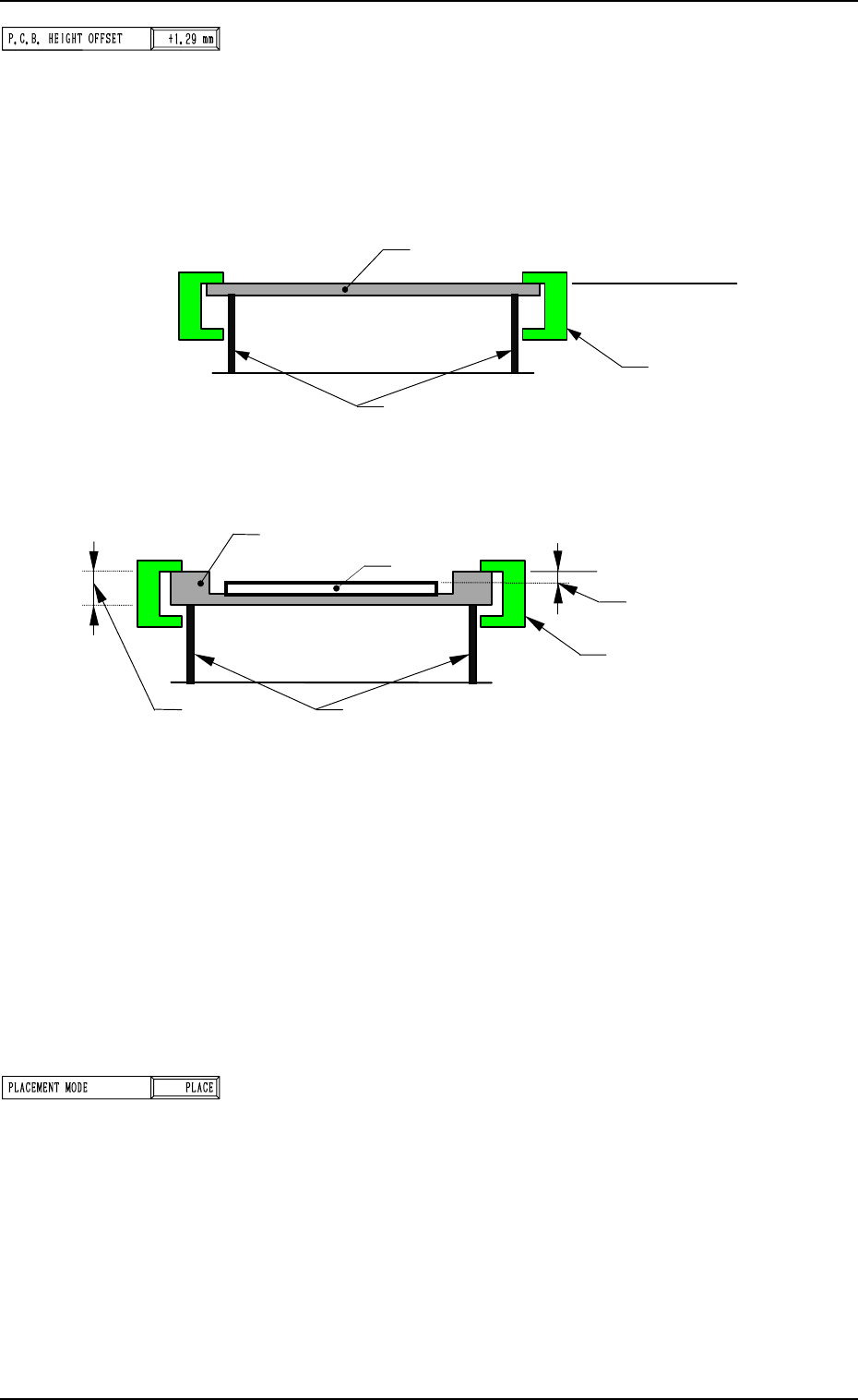
P.C.B. HEIGHT OFFSET
When a P.C.B. on a jig P.C.B. (such as a mother board) is
positioned, the upper surface level of the P.C.B. may extend
beyond the reference plane. In this case, set the offset data.
The head can be slid uniformly up and down according to the
offset data without changing each component library data
(placement level) for head descending distance at placement.
2. Pattern Program
P.C.B
.
Upper Surface of P.C.B.
Reference Plane
Clamp Plates
Chute
(Normal Case)
Jig P.C.B.
Upper Surface of P.C.B.
Reference Plane
Clamp Plates
P.C.B. Level
Chute
P.C.B.
T (Thickness)
(Jig P.C.B. Used)
Fig. 2.11
When the upper surface of the P.C.B. extends beyond the ref-
erence plane as shown in Fig. 2.11, enter plus data (a param-
eter with a plus (+) sign) to increase the head descending dis-
tance at placement.
The effective range varies depending on the components to be
placed.
In the case of normal P.C.B.’s for which a special jig P.C.B. is
not used, set “0” (zero) in the data box.
Note: When a jig P.C.B. is used, consult our sales personnel
separately for details.
PLACEMENT MODE
“PLACE” or “PASS” mode can be selected.
• When pattern program data in “PASS” mode is set for auto-
matic operation, the vacuum pump motor is automatically
turned off.
Fig. 2.10
9910-001 2-15 Tg0247-PM-PM
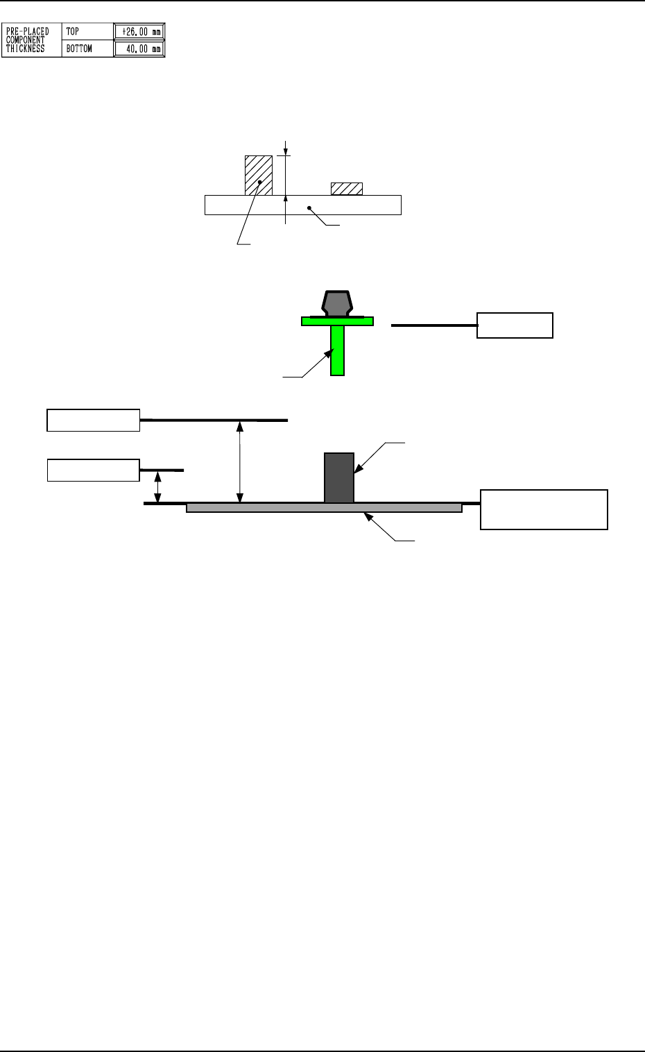
PRE-PLACED COMPONENT THICKNESS
TOP
When some components are placed previously (in advance) on
the top of a P.C.B. in the upstream line (input machine, etc.) and
the P.C.B. is already transferred to the machine, be sure to enter
the thickness of the highest component of all in the data box.
2. Pattern Program
L-Axis Origin
Reference: Upper Surface
of P.C.B.
Lower Pass Line
Previously-Placed Component
(including the already-placed component)
8.5 mm
(Design Dimension)
P. C. B.
Upper Pass Line
28 mm
(Design Dimension)
Nozzle
P.C.B.
Tallest Previously-Placed Component
Fig. 2.12
Fig. 2.13
Lower Pass Line : This line is the lowest level for the X/Y
beam movement when the thickness of a
previously-placed component (already-
placed component) is 6.5 mm or less. When
this level is not maintained, a physical in-
terference with a structure occurs.
This level is also regarded as a focus level
for component recognition.
As no height regulation is made for the pre-
viously-placed components (already-placed
components) during the X/Y beam move-
ment (component picks, component recog-
nition, component discharge operation, etc.)
outside the P.C.B. area (outside the area
where a P.C.B. is located for component
placement), the X/Y beam moves, keeping
the lower ends of the nozzles (without
picked components) and the lowest ends of
the picked components in this level.
Upper Pass Line : This line is the lowest level for the X/Y
beam movement when the thickness of a
previously-placed component (already-
placed component) is more than 6.5 mm.
(Only in the P.C.B. area)
9910-001 2-16 Tg0247-PM-PM