2OM-1064-002.pdf - 第157页
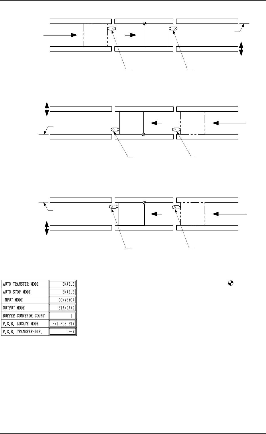
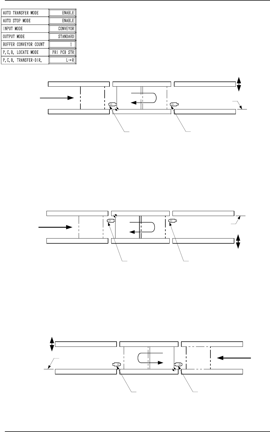
TIM-5100FL P .C.B. Transfer Reference: Front Side of Machine P .C.B. Transfer : L → R P .C.B. Positioning Reference: L-FRONT 2. P .C.B. TRANSFER MODE SET-UP Display A L Conveyor (Output Conveyor) R Conveyor (Input Convey…
[PLACE REF.] (Placement Coordinates Reference: )
The placement coordinates reference is given priority for
positioning.
Scope of Positioning
(1) The P.C.B.’s at Standby Position A in the figures be-
low are sent ahead of the P.C.B. stoppers for position-
ing.
(2) An action takes place to bring the P.C.B. back to the
P.C.B. stopper for positioning.
(3) The P.C.B. backup base ascends and works to position
the P.C.B. vertically and horizontally (alignment in Y
direction).
Note: Because an action takes place to return the P.C.B.
at P.C.B. positioning, the P.C.B. transfer time be-
comes longer, compared with the time required
when “PRI PCB STR” is set in the data box.
TIM-5100RR
A
L Conveyor
(Output Conveyor)
R Conveyor
(Input Conveyor)
L Conveyor
P.C.B. Stopper
R Conveyor
P.C.B. Stopper
P Conveyor
(P.C.B. Positioning Section)
P.C.B. Transfer
Reference
P.C.B.
P.C.B. Flow Direction
Movable
Side
TIM-5100FR
L Conveyor
(Output Conveyor)
R Conveyor
(Input Conveyor)
L Conveyor
P.C.B. Stopper
R Conveyor
P.C.B. Stopper
P Conveyor
(P.C.B. Positioning Section)
P.C.B. Transfer Reference
A
P.C.B.
P.C.B. Flow Direction
Movable
Side
L Conveyor
P.C.B. Stopper
TIM-5100RL
L Conveyor
(Input Conveyor)
R conveyor
(Output Conveyor)
R Conveyor
P.C.B. Stopper
P Conveyor
(P.C.B. Positioning Section)
P.C.B. Transfer Reference
P.C.B.
Movable
Side
P.C.B. Flow Direction
A
Fig. 3.4-2
2. P.C.B. TRANSFER MODE SET-UP Display
Fig. 3.4-3
Fig. 3.4-4
9910-001 3-8 Tg0247-PM-PM
TIM-5100FL
P.C.B. Transfer Reference: Front Side of Machine
P.C.B. Transfer : L → R
P.C.B. Positioning Reference: L-FRONT
2. P.C.B. TRANSFER MODE SET-UP Display
A
L Conveyor
(Output Conveyor)
R Conveyor
(Input Conveyor)
L Conveyor
P.C.B. Stopper
R Conveyor
P.C.B. Stopper
P Conveyor
(P.C.B. Positioning Section)
P.C.B. Transfer
Reference
P.C.B.
P.C.B. Flow Direction
Movable
Side
Placement Reference
Placement Reference
R Conveyor
(Output Conveyor)
L Conveyor
(Input Conveyor)
L Conveyor
P.C.B. Stopper
R Conveyor
P.C.B. Stopper
P Conveyor
(P.C.B. Positioning Section)
P.C.B.
P.C.B. Flow Direction
Movable
Side
P.C.B. Transfer
Reference
A
Placement Reference
R Conveyor
(Output Conveyor)
L Conveyor
(Input Conveyor)
L Conveyor
P.C.B. Stopper
R Conveyor
P.C.B. Stopper
P Conveyor
(P.C.B. Positioning Section)
P.C.B. Transfer Reference
P.C.B.
P.C.B. Flow Direction
Movable
Side
A
Fig. 3.5-1
TIM-5100RL
P.C.B. Transfer Reference: Rear Side of Machine
P.C.B. Transfer : L → R
P.C.B. Positioning Reference: L-BACK
Fig. 3.5-2
TIM-5100FR
P.C.B. Transfer Reference: Front Side of Machine
P.C.B. Transfer : R → L
P.C.B. Positioning Reference: R-FRONT
Fig. 3.5-3
9910-001 3-9 Tg0247-PM-PM
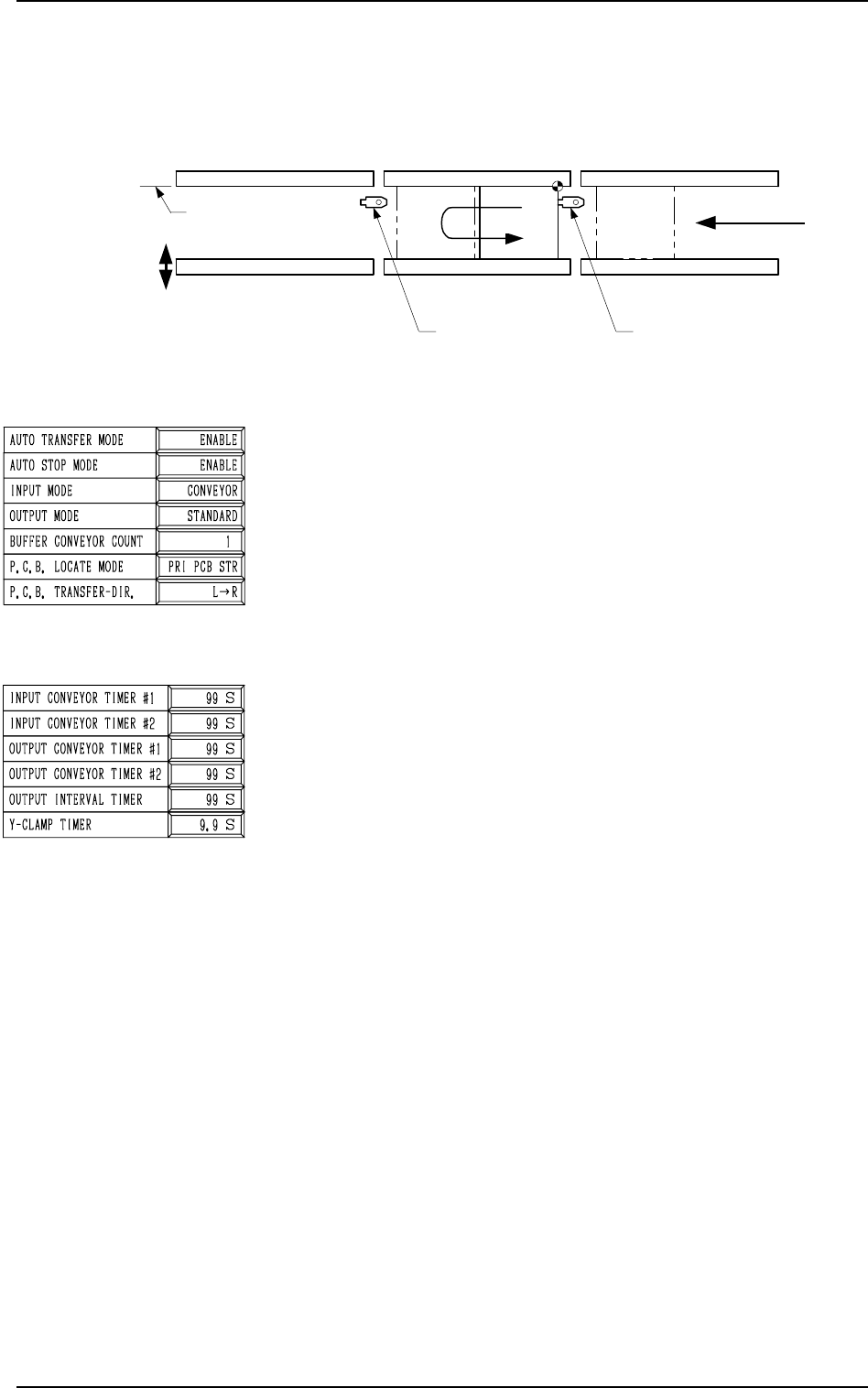
Fig. 3.5-4
P.C.B. TRANSFER-DIR.
Set “L → R” or “R → L” in the data box to specify the P.C.B.
transfer direction.
• [L → R]
P.C.B.’s are transferred from left to right.
• [R → L]
P.C.B.’s are transferred from right to left.
Note: Whenever the set parameter is changed, the zeroing
operation must be performed.
INPUT CONVEYOR TIMER #1
The operating time (P.C.B. reception from the input machine)
of the input conveyor can be limited by this timer.
This timer measures the operating time of the input conveyor
and is used to detect an interrupted P.C.B.
• Add 2 seconds (approx.) to the time required for P.C.B. re-
ception from the input machine and set.
• Data Input Range: 0 to 99 seconds
INPUT CONVEYOR TIMER #2
The operating time of the input conveyor can be limited by
this timer when a P.C.B. is transferred inside the machine by
the input conveyor.
This timer measures the operating time of the input conveyor
and is used to detect an interrupted P.C.B.
Note: This time is also used for the timer of EL/ER conveyor
(option).
• Data Input Range: 0 to 99 seconds
OUTPUT CONVEYOR TIMER #1
The operating time of the output conveyor can be limited by
this timer when a P.C.B. is received by the output machine.
• Add 2 seconds (approx.) to the time required for P.C.B. trans-
fer to the output machine and set.
• Data Input Range: 0 to 99 seconds
2. P.C.B. TRANSFER MODE SET-UP Display
TIM-5100RR
P.C.B. Transfer Reference: Rear Side of Machine
P.C.B. Transfer : R → L
P.C.B. Positioning Reference: R-BACK
A
L Conveyor
(Output Conveyor)
R Conveyor
(Input Conveyor)
L Conveyor
P.C.B. Stopper
R Conveyor
P.C.B. Stopper
P Conveyor
(P.C.B. Positioning Section)
P.C.B. Transfer
Reference
P.C.B.
P.C.B. Flow Direction
Movable
Side
Placement Reference
0103-003 3-10 Tg0247-PM-PM