2OM-1064-002.pdf - 第154页
OUTPUT MODE Select “ST ANDARD” or “INTER V AL” according to the P .C.B. loading system of the output machine. • “ST ANDARD” Mode When the output machine is connected with our machine (a component placement machine, a dis…

AUTO STOP MODE
“ENABLE” or “DISABLE” can be set in this data box. When
“ENABLE” is set, the automatic stop function is selected.
• When “ENABLE” (standard mode) is set in the data box,
the automatic stop function works in the following cases.
(1) When automatic operation of the machine is started by
pressing the [START] button without any P.C.B. on the
machine, the machine is waiting for a P.C.B. to be sent
from the input machine and detects that “RUN” signal
has stopped coming from the input machine. When the
machine is set under this condition for two seconds, it
stops running.
This function is based on the concept that it will be un-
necessary to continue automatic operation of the machine
when there is no P.C.B. on the machine and the input
machine is not running automatically because it is appar-
ent that no P.C.B. can be transferred to the machine any-
more.
(2) The automatic operation of the machine stops when a
P.C.B. on the machine is processed, there is no unproc-
essed P.C.B. left on the machine, and the input machine
is stopped after the last processed P.C.B. on the machine
has been discharged to the output machine.
Note: When the machine is connected to another one
manufactured by another company, this function
may not be activated.
• When “DISABLE” is set in the data box and the machine is
set under the above-described condition (1) and (2), the
machine is not set in the “STOP” mode and is kept in the
“WAIT” mode.
INPUT MODE
Select “CONVEYOR”, “PUSHER” or “CONVEYOR 2” ac-
cording to the P.C.B. unloading system of the input machine.
• “CONVEYOR” Mode (Standard)
The input conveyor is activated to receive a P.C.B. from the
input machine when the P.C.B. transfer signal is received
from the input machine.
• “PUSHER” Mode
The pusher of the input machine forces a P.C.B. out to the
input conveyor of the machine.
• “CONVEYOR 2” Mode
Set this when the machine is connected with a machine of
another brand.
When the sensor at the end of the input conveyor detects a
P.C.B., the P.C.B. transfer operation starts.
Note: The P.C.B. requiring signal is not turned off and
transmitted to the input machine until the P.C.B. re-
ceiving operation is completed.
2. P.C.B. TRANSFER MODE SET-UP Display
9910-001 3-5 Tg0247-PM-PM

OUTPUT MODE
Select “STANDARD” or “INTERVAL” according to the P.C.B.
loading system of the output machine.
• “STANDARD” Mode
When the output machine is connected with our machine (a
component placement machine, a dispenser, a printer, or a
multi-functional component placement machine), set
“STANDARD” in the data box.
When the P.C.B. requirement signal is received from the
output machine, the P.C.B. transfer signal of the machine is
turned ON and a P.C.B. is discharged to the output machine
by the output conveyor.
When the P.C.B. requirement signal is not turned OFF within
the specified time after P.C.B. unloading action has started,
the machine stops in an error condition.
• “INTERVAL” Mode
When the machine receives the P.C.B. requirement signal
from the output machine, it does not transmit any response
signal (no handshaking) and starts discharging P.C.B.’s.
The conveyor stops when the output conveyor timer has
reached the specified time.
When the requirements for P.C.B. output are fulfilled after
the conveyor has stopped and the output interval timer has
reached the time set in the “OUTPUT INTERVAL TIMER”
data box, the machine starts the P.C.B. output operation.
(No Error Detection)
BUFFER CONVEYOR COUNT
Set the number of P.C.B. buffers on the input conveyor in this
data box.
• “0”, “1”, or “2” can be set in the data box.
Note: The parameter “2” becomes valid only EL/ER conveyor
(option) is installed on the input side.
0103-003 3-6 Tg0247-PM-PM
2. P.C.B. TRANSFER MODE SET-UP Display
P.C.B. LOCATE MODE
Set the sequence in which a P.C.B. should be transferred and
positioned.
Select “PRI PCB STR” or “PLACE REF.”.
“PRI PCB STR” : Select this when the placement coordinates
reference for the P.C.B. must be specified
on the opposite side of the P.C.B. stopper
location for P.C.B. positioning.
“PLACE REF.” : Select this when the placement coordinates
reference must be specified on the side
where the P.C.B. is pushed against the
P.C.B. stopper.
Refer to “6.5 P.C.B. Transfer of Section 1 in Volume 1” for
details.
Notes: (a) The direction of the P.C.B. stopper block is ad-
justed in compliance with the setting upon ship-
ment of the machine.
When the setting is changed, it is required to
change the direction of the P.C.B. stopper block
according to the changed setting.
Refer to “Section 2 Adjustment of P.C.B. Posi-
tioning Section in Volume 5” for details.
(b) Push the P.C.B. against the P.C.B. stopper for
positioning.
When an area of the P.C.B. has a cutout, etc.,
and is pushed against the P.C.B. stopper, the
P.C.B. cannot be positioned correctly.
(c) When a P.C.B. is positioned by the pilot pin (op-
tion), set “PLACE REF.” in the data box.
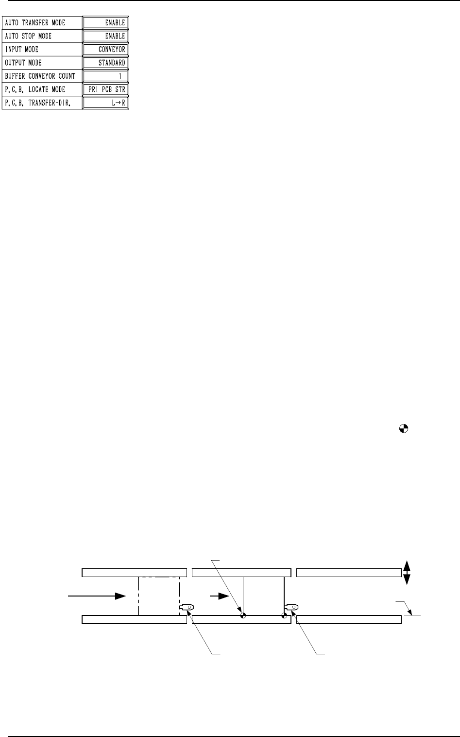
[PRI PCB STR] (Placement Coordinates Reference: )
P.C.B.’s are positioned based on the stopper located ahead
in the P.C.B. flow direction.
Scope of Positioning
(1) The P.C.B.’s at standby position A in the figures be-
low are sent to the P.C.B. stoppers.
(2) The P.C.B. backup base ascends and works to position
the P.C.B. vertically and horizontally (alignment in Y
direction).
2. P.C.B. TRANSFER MODE SET-UP Display
9910-001 3-7 Tg0247-PM-PM
L Conveyor
(Input Conveyor)
R conveyor
(Output Conveyor)
L Conveyor
P.C.B. Stopper
R Conveyor
P.C.B. Stopper
P Conveyor
(P.C.B. Positioning Section)
Movable Side
P.C.B. Transfer Reference
P.C.B.
Note b
P.C.B. Flow Direction
TIM-5100FL
A
Fig. 3.4-1