2OM-1064-002.pdf - 第124页
0004-002 2-112 Tg0247-PM-PM 4. P A TTERN PROGRAM Display 4.5.2 Editing of T ray Component Data (Option) The following example is based on the component data (T ray L). T o edit the component data (T ray R), the “COMPONEN…

4. PATTERN PROGRAM Display
(6) Edit the component data as follows.
• When the [C] key is selected, a control command can be entered. Press-
ing the [COMMENT] key also makes it possible to enter a comment.
• When the [COMPONENT ID INITIALIZED] key is pressed, the key
turns red. Pressing the [SET] key subsequently clears the component
ID which corresponds to the selected feeder No. (FDR NO).
Ref.: When the [COMPONENT ID INITIALIZED] key in red is
pressed again, the component ID initialization mode is can-
celled.
• When the [VIB. STICK UNIT] key is pressed, the lane (FDR NO) is
set to the slot No. of the feeder on the vibratory stick feeder unit.
Refer to “2.5.1 Tape Feeders of Section 2” for the setting of the vibra-
tory stick feeder unit.
• When the [AUTO] key beside the label “CMPNT ID LIST CURSOR”
is pressed, the line cursor in the list box automatically moves to the
component ID for the selected feeder slot No. (FDR NO).
When the [LOCK] key is pressed, the line cursor in the list box is
locked (fixed). However, it can be moved only with the [ ] or the [ ]
key beside the list box.
• Press the [STEP INSERT] or the [STEP DELETE] key to insert or
delete the data line (step) of the feeder slot No. where the line cursor is
located.
• When the [PROGRAM CHECK] key is pressed, the edited pattern
program is checked.
(7) When the [RTN] key is pressed, the “COMPONENT DATA” display for
“TAPE A” appears on the screen.
0004-002 2-111 Tg0247-PM-PM
0004-002 2-112 Tg0247-PM-PM
4. PATTERN PROGRAM Display
4.5.2 Editing of Tray Component Data (Option)
The following example is based on the component data (Tray L).
To edit the component data (Tray R), the “COMPONENT DATA -TRAY-”
display for “Tray R” must also be opened.
Operation Procedure
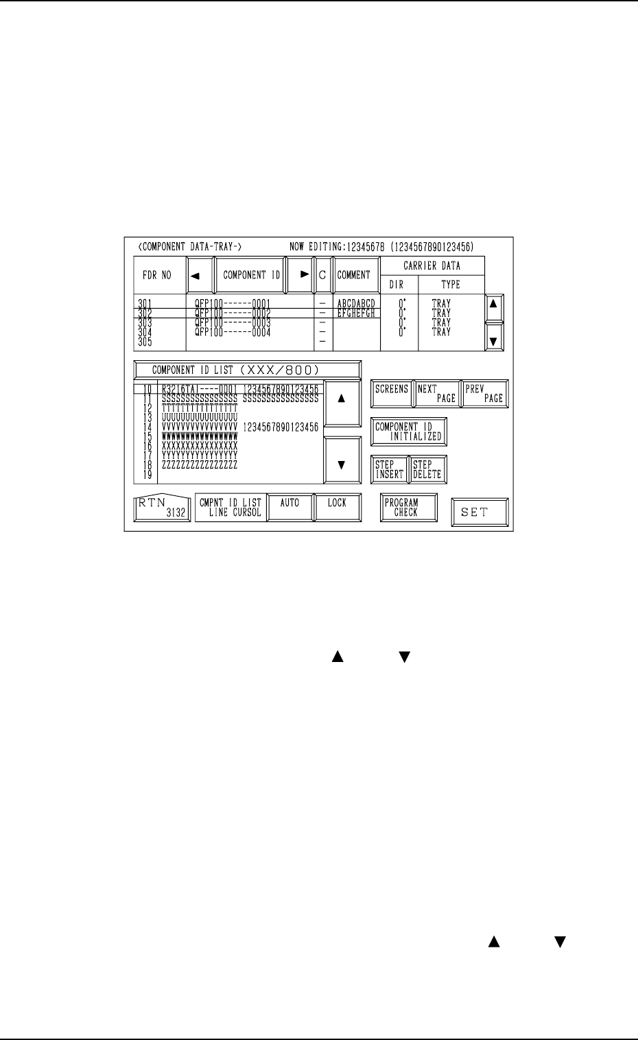
(1) When the “DATA EDIT” key is pressed at the “COMPONENT DATA -
TRAY-” display (Fig. 2.104) for “Tray L”, the following display appears
on the screen.
Fig. 2.106
(2) Move the line cursor to the feeder slot No. (FDR NO) of the data to be
edited.
(3) Press the [COMPONENT ID] key to enable the selection of component
IDs.
(4) Select a component ID with the [ ] or the [ ] key beside the “COMPO-
NENT ID LIST (XXX/800)” list box.
(5) Press the [SET] key. The selected component ID is set.
(6) Edit the component data as follows.
• When the [C] key is selected, a control command can be entered. Press-
ing the [COMMENT] key also makes it possible to enter a comment.
• When the [COMPONENT ID INITIALIZED] key is pressed, the key
turns red. Pressing the [SET] key subsequently clears the component
ID which corresponds to the selected feeder No. (FDR NO).
Ref.: When the [COMPONENT ID INITIALIZED] key in red is
pressed again, the component ID initialization mode is can-
celled.
• When the [AUTO] key beside the label “CMPNT ID LIST CURSOR”
is pressed, the line cursor in the list box automatically moves to the
component ID for the selected feeder slot No. (FDR NO).
When the [LOCK] key is pressed, the line cursor in the list box is
locked (fixed). However, it can be moved only with the [ ] or the [ ]
key beside the list box.
4. PATTERN PROGRAM Display
• Press the [STEP INSERT] or the [STEP DELETE] key to insert or
delete the data line (step) of the feeder slot No. where the line cursor is
located.
• When the [PROGRAM CHECK] key is pressed, the edited pattern
program is checked.
(7) When the [RTN] key is pressed, the “COMPONENT DATA -TRAY-”
display appears on the screen.
• When one of the [TRAY L] keys is pressed at the “COMPONENT
DATA -TRAY-” display for “Tray L” or “Tray R”, the “COMPONENT
DATA -TRAY-” display for the tray feeder unit (Tray L) installed on
the left side appears on the screen. Pressing one of the [TRAY R] keys
opens the “COMPONENT DATA -TRAY-” display for the tray feeder
unit (Tray R) on the right side.
4.5.3 Editing of Tray Steps Information Data (Option)
Operation Procedure
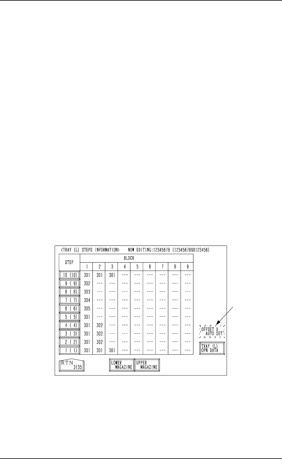
(1) When the [TRAY STEP INFO] key is pressed at the “COMPONENT
DATA -TRAY-” display (Fig. 2.104) for “Tray L”, the following display
appears on the screen.
While the system is in the edit mode of the component data for “Tray L”,
the “COMPONENT DATA -TRAY-” display shows the step information
for “Tray L”. In the edit mode of the component data for “Tray R”, the
display shows the step information for “Tray R”.
Fig. 2.107
• Press the [LOWER MAGAZINE] key to select the lower magazine.
Pressing the [UPPER MAGAZINE] key selects the upper magazine.
Note: The [OFFSET X AUTO SET] key *1 may not appear, depending
on how the feeder Nos. (FDR NO) are set.
Consult our sales personnel for details.
*1
0004-002 2-113 Tg0247-PM-PM