2OM-1064-002.pdf - 第70页
9910-001 2-58 Tg0247-PM-PM 2. Pattern Program H (mm) Set the placement height of component. T o increase the descending stroke of the head for component placement, a plus value must be entered. • The set parameter is use…
9910-001 2-57 Tg0247-PM-PM
2. Pattern Program
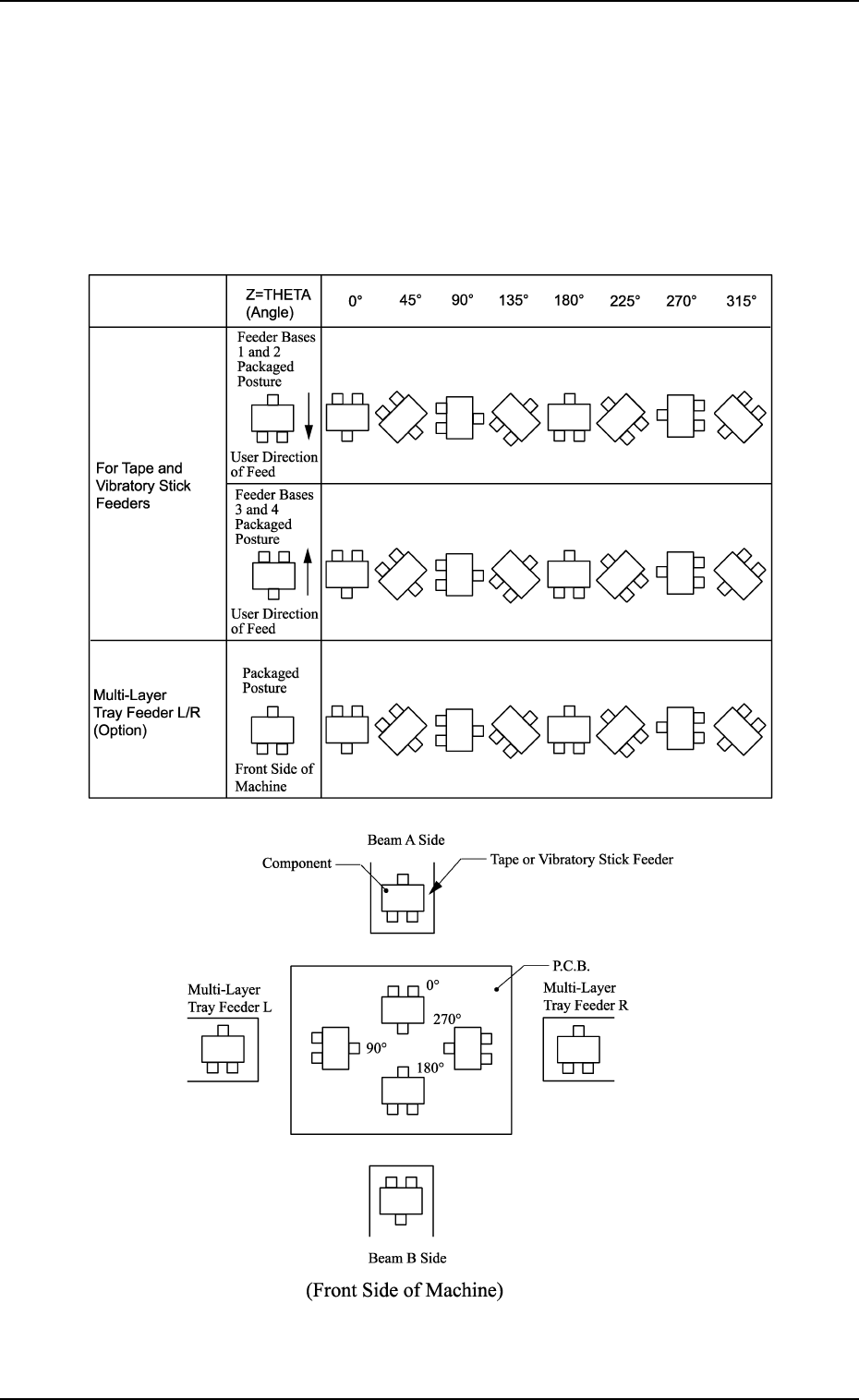
Z=THETA (Angle)
Set component placement angle data Z.
• Data Input Range: 0°00´ to 359°59´
• Offset value must be entered as placement angle offset in the data field
of step P-0000 labeled “Z=THETA”.
The offset values can be entered in the range “-99°99´ to +99°99´ ” with
+ or - sign.
Note: The following shows the placement angles changed from the pack-
aged posture of a component.
9910-001 2-58 Tg0247-PM-PM
2. Pattern Program
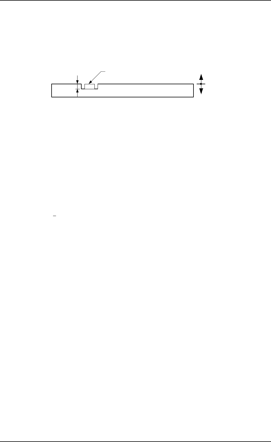
H (mm)
Set the placement height of component.
To increase the descending stroke of the head for component placement, a
plus value must be entered.
• The set parameter is used to cope with concave sections of a P.C.B. and
convex sections of a daughter P.C.B.
• The “H” data in the P-0000 step is reflected on all steps.
Reference Plane
P.C.B.
Component
+
-
FDR
Set a feeder No. (component-allocated slot No.).
• Data Input Range
101 to 109, 121 to 139, 201 to 219, 221 to 239
Note: The feeder No. set here must be specified in the component data.
• Components are picked up from the set feeder No. (slot No.).
The component No. offset is added to the feeder slot No. from which
components are actually picked up.
S
Shown is the sequence in which components are picked up.
By specifying “1” or “2” as the S data, a pair of placement steps can be
made.
: Individual Component Pick-Up/Placement
This shows that the number of cutting blocks is “1 step”.
1 : Simultaneous Pick-Up
The number of cutting blocks is “2 steps” (current and subsequent steps).
Components are recognized and placed in the order specified in the
placement data.
2 : Pick-Up Priority
The number of cutting blocks is “2 steps” (current and subsequent steps).
Components are picked up, recognized and placed in the order speci-
fied in the placement data.
Note: When the simultaneous pick-up and chuck position automatic fol-
low-up functions are used together, the chuck position automatic
follow-up function works based on the results of the component
recognition for the first step of the paired two placement steps. There-
fore, a hindrance may be caused at the other component pick-up
position. Especially, when small components are picked up simul-
taneously or components which require delicate picks are handled,
it is recommended that the pick-up priority function should be used.
• To designate the individual pick-up/placement, set “-” as the S
data.
In the following cases, “Individual Pick-Up/Placement” must be
specified because no pairing (2-step processing) can be made.
• Components whose dimension (width) exceeds 50 mm are
handled. (Component Collision due to Rotation)
• Components subjected to the divided recognition are handled.

• To designate the simultaneous pick-up (“1” to be set as “S” data)
Designation Possible Designation Impossible
• A pair of components which meet the following
requirements
• Pairing Components between Tape Feeders
• The distance between two picked
components is “108 mm”.
(Based on the distance (108 mm) between
the nozzle rotational centers of Heads #1 and
#2)
Example:
Using the 8 mm tape feeder
Lane Pitch (18 mm) × 6 Lanes =
108 mm
Refer to “7. Construction of Feeder Carriage
of Section 1 in Volume 1” for the
combination of the tape feeders.
• Either one of the data to be paired is the
component of the vibratory stick feeder.
• Pairing of Components between Vibratory
Stick Feeders
• Pairing of Components between Vibratory
Stick and Tape Feeders
•
Pairing
of Components between Vibratory
Stick and Step-Stacking Stick Feeders
(Reserved Function)
• Either one of the data to be paired is the
component of the step-stacking stick feeder.
(Reserved Function)
• Pairing of Components between Step-
Stacking Stick Feeders
• Pairing of Components between Step-
Stacking Stick and Tape Feeders
• Pairing of Components between Step-
Stacking Stick and Vibratory Stick Feeders
• Eccentric Pick-Up Designated Components
(Chuck Location Adjustment X and Y in
Component Library Data)
• Components for which “ADHESIVE” is set in
the “CARRIER TYPE” data box in the
component library data
• Pairing of Components between Tray Feeders
• The distance between two components to be
supplied is not “108 mm”.
9910-001 2-59 Tg0247-PM-PM
2. Pattern Program