2OM-1064-002.pdf - 第194页
Fig. 5.26 BEAM A HEAD #1, X (horizontal), Y (vertical) This offset data is used to set the distance between the scan- ning coordinate center (actual position) of the P .E.C. camera on Beam A and the rotational center of …
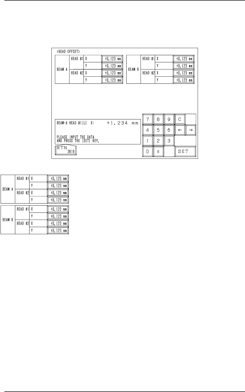
Fig. 5.25
BEAM A/BEAM B HEAD #1/HEAD #2, X (horizontal), Y (ver-
tical)
This offset data is used to correct the positional deviation
(placement coordinates) caused due to the deviation of
straightness (skew) of each individual head up/down axis
guides. The set parameters are added to the amount of beam
movement (travel) for component placement.
This offset data is automatically calculated through teaching
operation which is performed, using the jig component sta-
tioned at the teaching plate section inside the machine.
5. HEAD OFFSET Display
When the [HEAD OFFSET] key is pressed at the “OFFSET DATA” display,
the following display appears on the screen.
5. HEAD OFFSET Display
9910-001 5-23 Tg0247-PM-PM
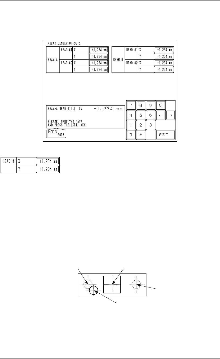
Fig. 5.26
BEAM A HEAD #1, X (horizontal), Y (vertical)
This offset data is used to set the distance between the scan-
ning coordinate center (actual position) of the P.E.C. camera
on Beam A and the rotational center of Head #1. The distances
deviating from the design values must be entered in each data
box. The parameters must be those viewed in the X/Y coordi-
nate system (PL-XY) for P.C.B. positioning.
• Design Values (distances between the center of P.E.C. cam-
era on Beam A and the rotational center of Head #1)
X : +54.000 mm
Y : +0.000 mm
When the rotational center of Head #1 is actually located at
the position shown in the figure below, the offset parameters
representing the X (horizontal) and Y (vertical) must be pro-
vided with plus (+) signs.
0004-002 5-24 Tg0247-PM-PM
6. HEAD CENTER OFFSET Display
6. HEAD CENTER OFFSET Display
When the [HEAD CENTER OFFSET] key is pressed at the “OFFSET DATA”
display, the following display appears on the screen.
Center of P.E.C. Camera on Beam A
Rotational Center (Design Position)
of Head #1 on Beam A
Actual Rotational Center of Head #2 on Beam A
Rotational Center (Design Position)
of Head #2 on Beam A
(Front Side of Machine)
Top View
Fig. 5.27
This offset data is automatically calculated through teaching
operation which is performed, using the jig component sta-
tioned at the teaching plate inside the machine.
Center of P.E.C. Camera on Beam A
Rotational Center (Design Position)
of Head #1 on Beam A
Actual Rotational Center of Head #2 on Beam A
Rotational Center (Design
Position) of Head #2 on Beam A
(Front Side of Machine)
Top View
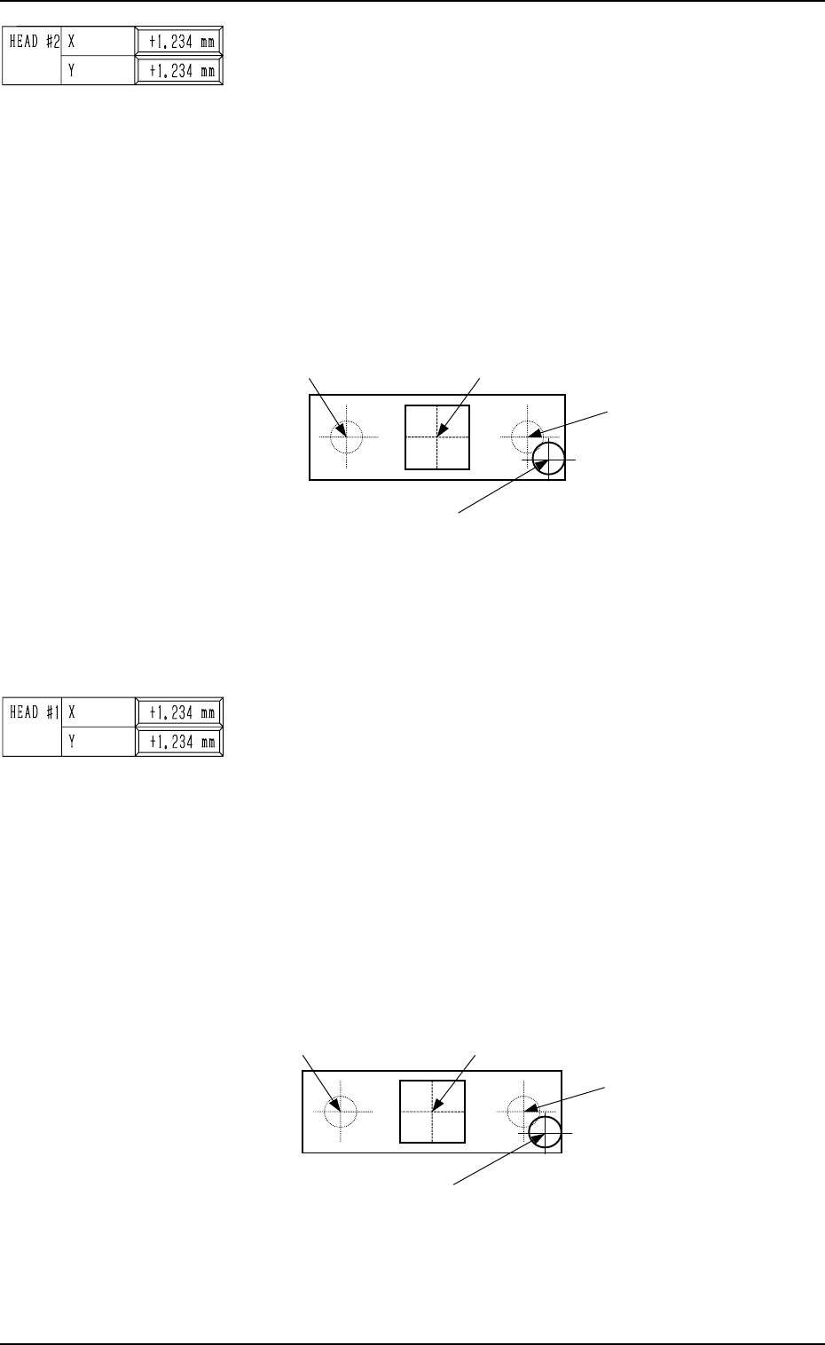
BEAM A HEAD #2, X (horizontal), Y (vertical)
This offset data is used to set the distance between the scan-
ning coordinate center (actual position) of the P.E.C. camera
on Beam A and the rotational center of Head #2. The distances
deviating from the design values must be entered in each data
box. The parameters must be those viewed in the X/Y coordi-
nate system (PL-XY) for P.C.B. positioning.
• Design Values (distances between the center of P.E.C. cam-
era on Beam A and the rotational center of Head #2)
X : -54.000 mm
Y : +0.000 mm
When the rotational center of Head #1 is actually located at
the position shown in the figure below, the offset parameters
representing the X (horizontal) and Y (vertical) must be pro-
vided with plus (+) signs.
6. HEAD CENTER OFFSET Display
0004-002 5-25 Tg0247-PM-PM
Center of P.E.C. Camera on Beam A
Rotational Center (Design Position)
of Head #2 on Beam B
Actual Rotational Center of Head #1 on Beam B
Rotational Center (Design Position)
of Head #1 on Beam B
(Front Side of Machine)
Top View
This offset data is automatically calculated through teaching
operation which is performed, using the jig component sta-
tioned at the teaching plate inside the machine.
BEAM B HEAD #1, X (Horizontal), Y (Vertical)
This offset data is used to set the distance between the scanning
coordinate center (actual position) of the P.E.C. camera on Beam
B and the rotational center of Head #1. The distances deviating
from the design values must be entered in each data box.
The parameters must be those viewed in the X/Y coordinate
system (PL-XY) for P.C.B. positioning.
• Design Values (distances between the center of P.E.C. cam-
era on Beam B and the rotational center of Head #1)
X : -54.000 mm
Y : +0.000 mm
When the rotational center of Head #2 is actually located at
the position shown in the figure below, the offset param-
eters representing the X (horizontal) and Y (vertical) must
be provided with plus (+) signs.
Fig. 5.28
This offset data is automatically calculated through teaching
operation which is performed, using the jig component sta-
tioned at the teaching plate inside the machine.
Fig. 5.29