2OM-1064-002.pdf - 第151页
2. P .C.B. TRANSFER MODE SET-UP Display 2. P .C.B. TRANSFER MODE SET-UP Display When the [P .C.B. TRANSFER MODE SET-UP] key is pressed at the “DE- VICE DA T A” display , the following display appears on the screen. Fig. …
1. DEVICE DATA Display
The P.C.B. transfer mode (P.C.B. reception from the input machine and trans-
fer to the output machine) and the device timers can be set.
When the [DEVICE DATA] key is pressed at the “DATA EDIT” display, the
following display appears on the screen.
Note: The -marked function is optional.
*1
*2
*3
1. DEVICE DATA Display
0103-003 3-2 Tg0247-PM-PM
Fig. 3.1
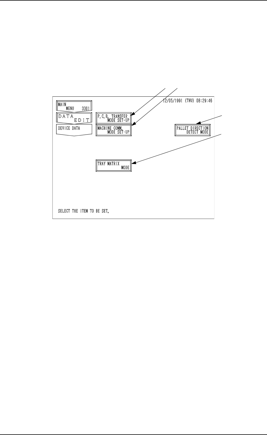
*1 [P.C.B. TRANSFER MODE SET-UP] Key
Various parameters can be set when P.C.B.’s are produced mainly in the in-
line system.
(P.C.B. transfer mode, conditions, etc., can be set.)
*2 [MACHINE COMM. MODE SET-UP] Key
The machine address can be set for data communication with an external
device (such as the programming device).
*3 [TRAY MATRIX MODE] Key (Option)
When this key is pressed, the “TRAY MATRIX MODE” display appears
on the screen, enabling you to designate the direction in which the tray
matrix should be updated.
(When it is necessary to keep the interchangeability with TIM-1000 and
TIM-1100 series, set “X DIR.” in the “TRAY MATRIX MODE” data box
at the “TRAY MATRIX MODE2 display.)
*4 PALLET DIRECTION DETECT MODE
When this key is pressed, the detection mode for the direction of the pallet,
when it is attached, can be set.
*4
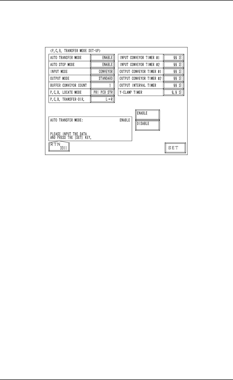
2. P.C.B. TRANSFER MODE SET-UP Display
2. P.C.B. TRANSFER MODE SET-UP Display
When the [P.C.B. TRANSFER MODE SET-UP] key is pressed at the “DE-
VICE DATA” display, the following display appears on the screen.
Fig. 3.2
9910-001 3-3 Tg0247-PM-PM
AUTO TRANSFER MODE
“DISABLE” or “ENABLE” can be set in this data box. When
“ENABLE” is set, the automatic P.C.B. transfer function is
selected.
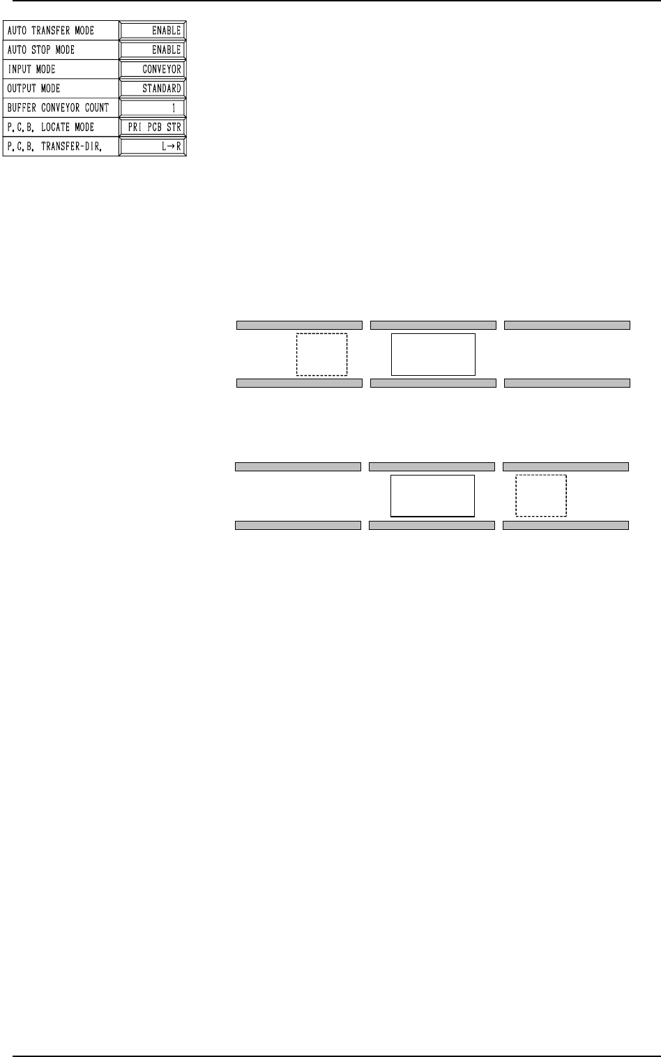
• When “DISABLE” (standard mode) is set in the data box,
P.C.B.’s are transferred as follows.
The finished P.C.B. (where components are already placed)
on the P.C.B. positioning section is discharged at the same
time when the subsequent P.C.B. is transferred to the P.C.B.
positioning section.
The finished P.C.B. on the P.C.B. positioning section is set
in the standby mode until the subsequent P.C.B. comes to
the A shown in Fig. 3.3.
2. P.C.B. TRANSFER MODE SET-UP Display
9910-001 3-4 Tg0247-PM-PM
A
P.C.B. TRANSFER [R
→
L]
P.C.B. Positioning Section
A
P.C.B. TRANSFER [L
→
R]
P.C.B. Positioning Section
Fig. 3.3
• When “ENABLE” is set in the data box, P.C.B.’s are trans-
ferred as follows.
When the X/Y beam has returned to its origin after compo-
nents are placed on the P.C.B. on the P.C.B. positioning sec-
tion, no P.C.B. is located on the A shown in Fig. 3.3, and the
conveyor transfer is not started up, the P.C.B. transfer is
activated and the finished P.C.B. is discharged to the output
machine.
This function works efficiently to avoid finished P.C.B. stag-
nation on the P.C.B. positioning section when the line bal-
ance between the machine and the input machine is not good.