2OM-1064-002.pdf - 第71页
• T o designate the simultaneous pick-up (“1” to be set as “S” data) Desi gnati on Possi ble Desi gnati on Impo ssibl e • A pa ir of c omp o n ent s w h ic h me et t h e fo l l o w i ng r equir ements • Pairin g Componen…
9910-001 2-58 Tg0247-PM-PM
2. Pattern Program
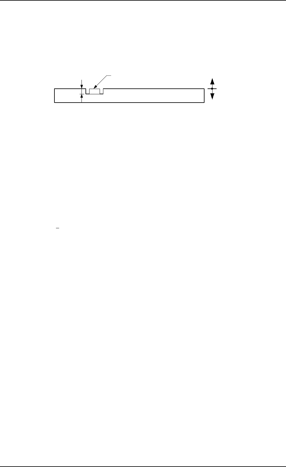
H (mm)
Set the placement height of component.
To increase the descending stroke of the head for component placement, a
plus value must be entered.
• The set parameter is used to cope with concave sections of a P.C.B. and
convex sections of a daughter P.C.B.
• The “H” data in the P-0000 step is reflected on all steps.
Reference Plane
P.C.B.
Component
+
-
FDR
Set a feeder No. (component-allocated slot No.).
• Data Input Range
101 to 109, 121 to 139, 201 to 219, 221 to 239
Note: The feeder No. set here must be specified in the component data.
• Components are picked up from the set feeder No. (slot No.).
The component No. offset is added to the feeder slot No. from which
components are actually picked up.
S
Shown is the sequence in which components are picked up.
By specifying “1” or “2” as the S data, a pair of placement steps can be
made.
: Individual Component Pick-Up/Placement
This shows that the number of cutting blocks is “1 step”.
1 : Simultaneous Pick-Up
The number of cutting blocks is “2 steps” (current and subsequent steps).
Components are recognized and placed in the order specified in the
placement data.
2 : Pick-Up Priority
The number of cutting blocks is “2 steps” (current and subsequent steps).
Components are picked up, recognized and placed in the order speci-
fied in the placement data.
Note: When the simultaneous pick-up and chuck position automatic fol-
low-up functions are used together, the chuck position automatic
follow-up function works based on the results of the component
recognition for the first step of the paired two placement steps. There-
fore, a hindrance may be caused at the other component pick-up
position. Especially, when small components are picked up simul-
taneously or components which require delicate picks are handled,
it is recommended that the pick-up priority function should be used.
• To designate the individual pick-up/placement, set “-” as the S
data.
In the following cases, “Individual Pick-Up/Placement” must be
specified because no pairing (2-step processing) can be made.
• Components whose dimension (width) exceeds 50 mm are
handled. (Component Collision due to Rotation)
• Components subjected to the divided recognition are handled.

• To designate the simultaneous pick-up (“1” to be set as “S” data)
Designation Possible Designation Impossible
• A pair of components which meet the following
requirements
• Pairing Components between Tape Feeders
• The distance between two picked
components is “108 mm”.
(Based on the distance (108 mm) between
the nozzle rotational centers of Heads #1 and
#2)
Example:
Using the 8 mm tape feeder
Lane Pitch (18 mm) × 6 Lanes =
108 mm
Refer to “7. Construction of Feeder Carriage
of Section 1 in Volume 1” for the
combination of the tape feeders.
• Either one of the data to be paired is the
component of the vibratory stick feeder.
• Pairing of Components between Vibratory
Stick Feeders
• Pairing of Components between Vibratory
Stick and Tape Feeders
•
Pairing
of Components between Vibratory
Stick and Step-Stacking Stick Feeders
(Reserved Function)
• Either one of the data to be paired is the
component of the step-stacking stick feeder.
(Reserved Function)
• Pairing of Components between Step-
Stacking Stick Feeders
• Pairing of Components between Step-
Stacking Stick and Tape Feeders
• Pairing of Components between Step-
Stacking Stick and Vibratory Stick Feeders
• Eccentric Pick-Up Designated Components
(Chuck Location Adjustment X and Y in
Component Library Data)
• Components for which “ADHESIVE” is set in
the “CARRIER TYPE” data box in the
component library data
• Pairing of Components between Tray Feeders
• The distance between two components to be
supplied is not “108 mm”.
9910-001 2-59 Tg0247-PM-PM
2. Pattern Program
• To designate the pick-up priority (“2” to be set as “S” data)
Designation Possible Designation Impossible
• Pairing of Components between Tape Feeders
• Pairing of Components between Tape and
Vibratory Stick Feeders
• Pairing of Components between Tape and Step-
Stacking Stick Feeders (Reserved Function)
• Pairing of Components between Tape and Tray
Feeders (Only Beam A Side)
• Pairing of Components between Vibratory Stick
Feeders
• Pairing of Components between Vibratory Stick
and Step-Stacking Stick Feeders (Reserved
Function)
• Pairing of Components between Vibratory Stick
and Tray Feeders (Only Beam A Side)
• Pairing of Components between Step-Stacking
Stick Feeders (Reserved Function)
• Pairing of Components between Step-Stacking
Stick and Tray Feeders (Only Beam A Side)
(Reserved Function)
• Pairing of Components between Tray Feeders
(Only Beam A Side)
• Eccentric Pick-Up Designated Components
(Chuck Location Adjustment X and Y in
Component Library Data)
• Components for which “ADHESIVE” is set in
the “CARRIER TYPE” data box in the
component library data
• Both components belong to the same area where
only one head can pick them up.
(Such components cannot be picked up by the
counteractive head because only the left head
can be used for the 6 lanes at the left end and
only the right head for the 6 lanes at the right
end.)
• Pairing of a component located at one side of the
X/Y beam and a component at the other side
2. Pattern Program
9910-001 2-60 Tg0247-PM-PM