2OM-1064-002.pdf - 第52页
*1 FDR NO • This shows the feeder Nos. of the component data. • This shows the actual feeder Nos. The numbers in ( ) indicate the feeder Nos. where component No. offset (reserved data) specified in the operation data is …
2.5.1 Tape Feeders
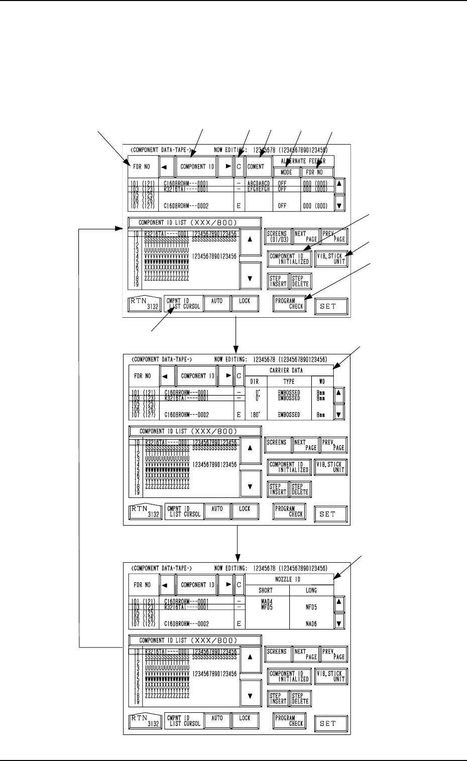
When the [DATA EDIT] key is pressed at the display (Fig. 2.31) for “TAPE
A”, the following display appears on the screen.
Every time the [SCREENS] key is pressed, another display appears on the
screen.
*1
*2
*3
*9
*8
*7
*4
*5
*6
*10
*11
*12
Fig. 2.34-1
[SCREENS] Key
Fig. 2.34-2
Fig. 2.34-3
0004-002 2-39 Tg0247-PM-PM
2. Pattern Program
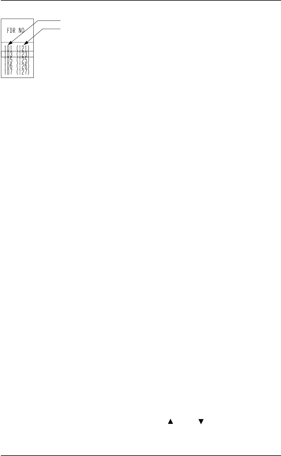
*1 FDR NO
• This shows the feeder Nos. of the component data.
• This shows the actual feeder Nos.
The numbers in ( ) indicate the feeder Nos. where component No.
offset (reserved data) specified in the operation data is added.
In the left figure (an example), “+20” is set as component No. offset.
Note: “- - -” appears in the “FDR NO” field for the feeder slots where
feeders cannot be installed.
*2 [COMPONENT ID] Key
Component IDs are shown in the corresponding field.
Set the IDs of the components to be set at the related feeder slots (FDR
NO).
*3 [C] Key
Control commands are shown in the corresponding field.
“-” : This command validates the steps as component data.
“S” : This command invalidates the steps specified as component data.
When component placement is specified for the invalid step (FDR
NO) in the placement data, the machine automatically omits the
placement operation for the step.
In this case, the background color of the “FDR” data field related to
the invalidated step turns red at the “PLACEMENT DATA” dis-
play, indicating that the component placement is canceled.
“E” : This control command specifies the end of the component data.
(This step is handled as a valid step.)
“X” : This control command shows the end of component data and speci-
fies the step as an invalid step.
Remember this command as “X = S + E”.
*4 [COMMENT] Key
A comment can be entered for each step.
Up to 8 characters can be entered.
*5 “ALTERNATE FEEDER” [MODE] Key
“ON” or “OFF” can be set to determine whether or not the alternate feeder
function should be used.
*6 “ALTERNATE FEEDER” [FDR NO] Key
When a component pick-up error occurs continuously (Component Li-
brary: ERROR PROCESS DATA 1 and 2), the destination feeder No. for
alternate use can be specified.
*7 CMPNT ID LIST CURSOR
[AUTO] Key : When this key is pressed, the line cursor moves automati-
cally such that the set component IDs can easily be re-
ferred to during component ID editing. (Default)
[LOCK] Key : When this key is pressed, the line cursor is locked regard-
less of the set component IDs during component ID edit-
ing.
The cursor can be moved only with the [ ] or the [ ] key.
9910-001 2-40 Tg0247-PM-PM
2. Pattern Program
*8 [COMPONENT ID INITIALIZED] key
When this key is pressed, the key turns red, indicating that the initializa-
tion mode is set.
When the [SET] key is pressed in the initialization mode, the component
ID is deleted and left blank.
Once the initialization operation is performed, the initialization mode is
automatically canceled.
Ref.: Difference between the [COMPONENT ID INITIALIZED] and
[STEP DELETE] Keys
The [STEP DELETE] key is used to delete a feeder No. (FDR NO).
The [COMPONENT ID INITIALIZED] key is used to clear a com-
ponent ID.
*9 [VIB. STICK UNIT] Key
When this key is pressed, a vibratory stick feeder unit is registered for the
feeder No. at the line cursor position.
One vibratory stick feeder unit occupies six feeder slot Nos. (lanes).
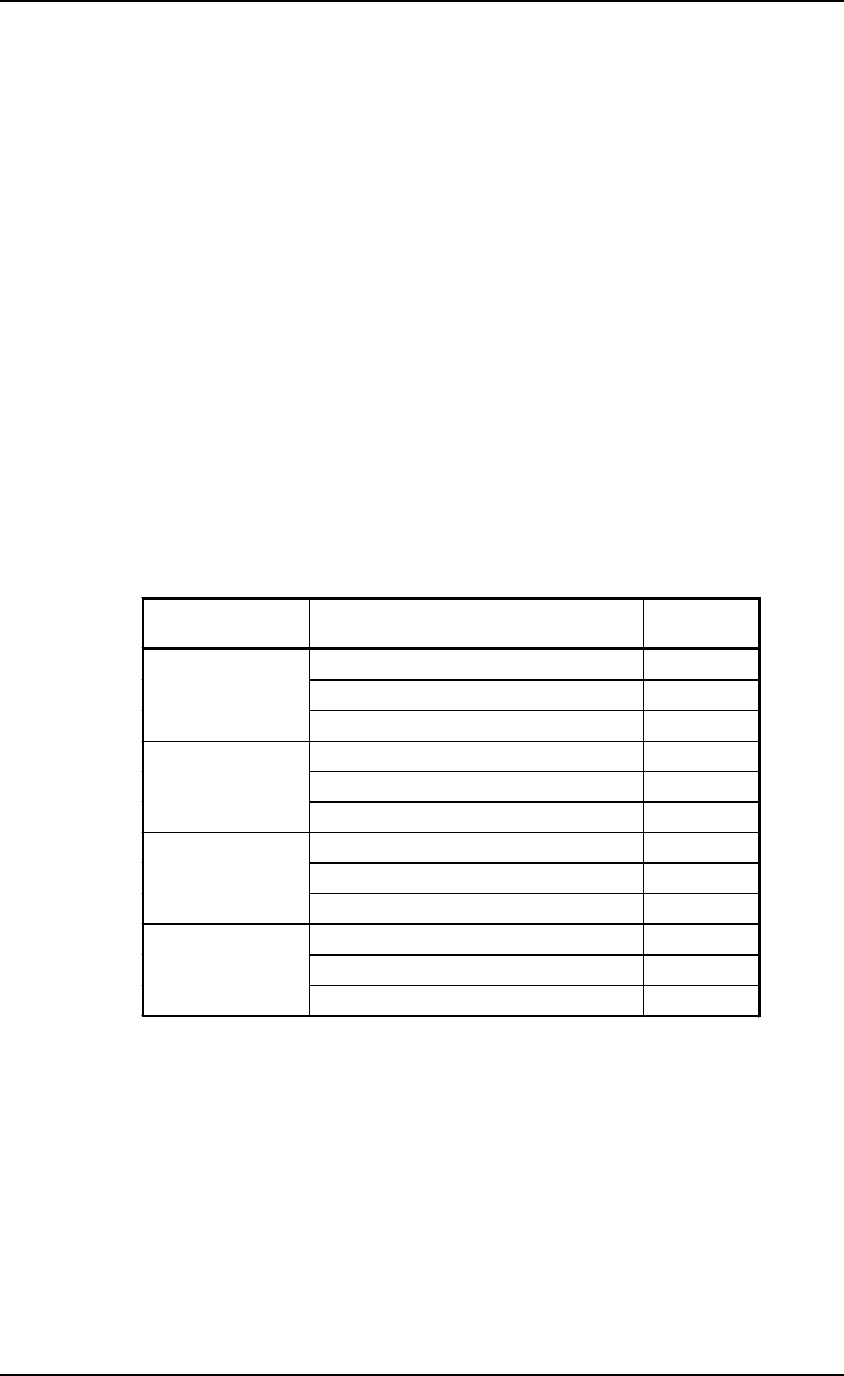
The following table shows the feeder slot Nos. (lanes) for which vibratory
stick feeder units can be registered.
The parameters for the vibratory stick feeder units can be entered at the
displays described in “2.5.2 Vibratory Stick Feeders of Section 2”.
*10 [PROGRAM CHECK] Key
0004-002 2-41 Tg0247-PM-PM
2. Pattern Program
Feeder Base
Nos.
Unit Nos.
Occupied Lanes
(FDR NO)
Vibratory Stick Feeder Unit 1 101 to 106
Feeder Base #1 Vibratory Stick Feeder Unit 2 107 to 112
Vibratory Stick Feeder Unit 3 113 to 118
Vibratory Stick Feeder Unit 4 121 to 126
Feeder Base #2 Vibratory Stick Feeder Unit 5 127 to 132
Vibratory Stick Feeder Unit 6 133 to 138
Vibratory Stick Feeder Unit 7 201 to 206
Feeder Base #3 Vibratory Stick Feeder Unit 8 207 to 212
Vibratory Stick Feeder Unit 9 213 to 218
Vibratory Stick Feeder Unit 10 221 to 226
Feeder Base #4 Vibratory Stick Feeder Unit 11 227 to 232
Vibratory Stick Feeder Unit 12 233 to 238
When this key is pressed, the edited pattern program is checked.
*11 CARRIER DATA, DIR, TYPE, WD
Shown in each data field are the parameters set in the component library
data.
*12 NOZZLE ID, SHORT, LONG
Shown in each data field are the parameters set in the component library
data.