2OM-1064-002.pdf - 第46页
[SCREENS] Key Fig. 2.31 *1 *6 *7 *2 *3 *10 *1 1 *9 *4 *5 *8 Fig. 2.31-1 Fig. 2.31-2 2. Pattern Program 9910-001 2-34 Tg0247-PM-PM [T APE A] Every time the [SCREENS] key is pressed at the display (Fig. 2.31), another disp…
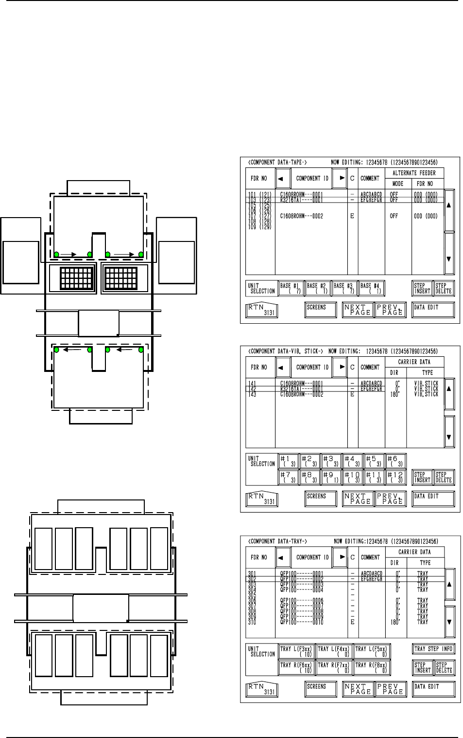
2.5 COMPONENT DATA Display
When the [TAPE [A] (F101-F139)], the [VIB STICK [A] (F141-F199)], or the
[TRAY L (F301-F599)] key is pressed at the “PATTERN PROGRAM EDIT”
display, the corresponding display (Fig. 2.31, 2.32, or 2.33) appears on the
screen.
When the [TAPE [B] (F201-F239)], the [VIB STICK [B] (F241-F299)], or the
[TRAY R (F601-F899)] key is pressed, the corresponding display (similar to
Fig. 2.31, 2.32, or 2.33) appears on the screen.
For Tape Feeders
701 to799
801 to899
FDR 101 to 139
101…119 121…139
Feeder
Base
2
FDR
239 to 201
Beam A
Multi-Layer
T
ray Feeder L
(Option)
601 to699301 to 399
401 to 499
501 to 599
219
…
201
239
…
221
Multi-Layer
Tray Feeder R
(Option)
The numbers represent feeder Nos. (FDR NO).
Beam B
Feeder
Base
1
Feeder
Base
3
Feeder
Base
4
Feeder
Base A
Feeder Base B
Fig. 2.30-1
Fig. 2.33
Fig. 2.32
Fig. 2.31
[TEAP A]
[VIB. STICK A]
[TRAY L]
FDR 141 to 199
FDR 299
to
241
Beam B
141
149
to
Feeder Base 1
151
159
161
169
171
179
181
189
191
199
261
269
251
259
241
249
291
299
271
279
281
289
Feeder Base 2
Feeder Base 3Feeder Base 4
Beam A
For Vibratory Stick Feeders
to
to
to
to
to
to
to
to to
to
to
Feeder Base A
Feeder Base B
Fig. 2.30-2
2. Pattern Program
0004-002 2-33 Tg0247-PM-PM
[SCREENS] Key
Fig. 2.31
*1
*6
*7
*2
*3
*10
*11
*9
*4 *5
*8
Fig. 2.31-1
Fig. 2.31-2
2. Pattern Program
9910-001 2-34 Tg0247-PM-PM
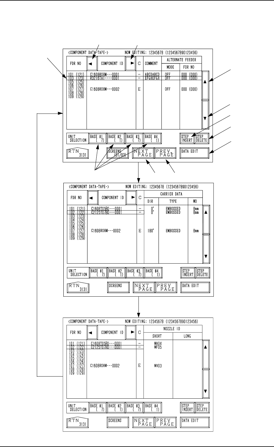
[TAPE A]
Every time the [SCREENS] key is pressed at the display (Fig. 2.31), another
display appears on the screen.
9910-001 2-35 Tg0247-PM-PM
2. Pattern Program
*1 The line cursor (blue) is used to select a step.
The line cursor can be moved up or down by pressing the [ ] or the [ ] key.
*2 [ ] Key
Press this key to move the line cursor upward.
When the line cursor is located at the top and this key is pressed, feeder
Nos. (FDR NO) scroll up. (Smaller Nos. appear one by one.)
*3 [ ] Key
Press this key to move the line cursor downward.
When the line cursor is located at the bottom and this key is pressed,
feeder Nos. (FDR NO) scroll down. (Larger Nos. appear one by one.)
*4 [NEXT PAGE] Key
Pressing this key opens the next page.
*5 [PREV. PAGE] Key
Pressing this key opens the previous page.
*6 [ ] Key
Pressing this key shifts the “COMPONENT ID” field horizontally to the
left, enabling to view the first part of component IDs.
*7 [ ] Key
Pressing this key shifts the “COMPONENT ID” field horizontally to the
right, enabling to view the comments (comments entered in the compo-
nent library).
*8 UNIT SELECTION [BASE #1], [BASE #2], [BASE #3],
and [BASE #4] Keys
When one of these keys is pressed, the component data related to the se-
lected feeder base unit appears on the screen.
When parameters are set in the component data, the background color is
turned green.
The numbers in ( ) show the step count of registered feeder Nos.