2OM-1064-002.pdf - 第96页
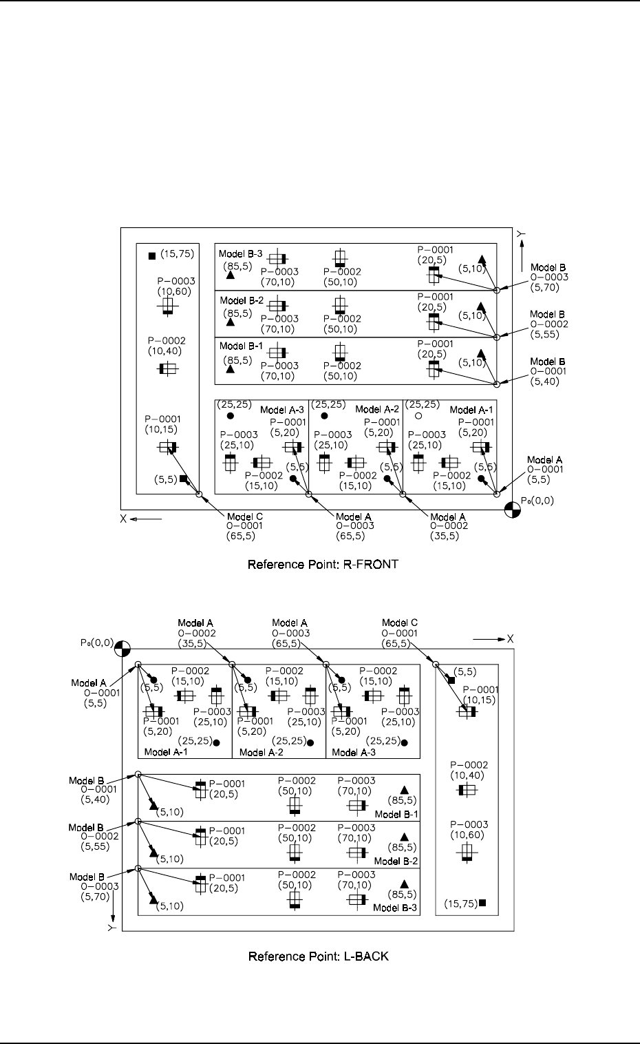
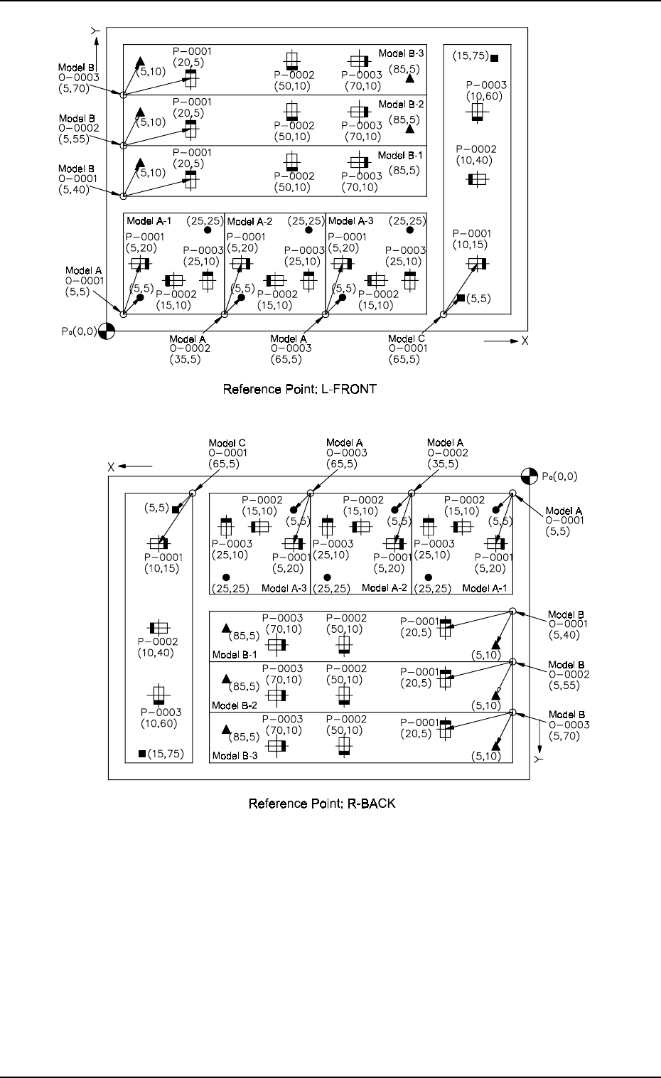
3. Example of Pattern Program Creation Fig. 2.64-4 Notes: (a) P 0 shows the P .C.B. positioning reference. (b) “O-0001, O-0002, and O-0003 for Model A”, “O-0001, O-0002, and O-0003 for Model B”, and “O-0001 for Model C” …
3. Example of Pattern Program Creation
3.2.5 Placement Data for Multi-Model Repetitive Patterns
(Application for Un)
(1) Pattern Sample
• The figure below shows that the mother board has seven unit P.C.B.’s
(6 unit P.C.B.’s for models A and B and 1 unit P.C.B. for model C).
Components are placed repeatedly in regular order on each unit P.C.B.
for models A and B, forming repetitive patterns. In the case of model
C, components are placed without forming any repetitive pattern.
9910-001 2-83 Tg0247-PM-PM
Fig. 2.64-2
Fig. 2.64-1
3. Example of Pattern Program Creation
Fig. 2.64-4
Notes: (a) P
0
shows the P.C.B. positioning reference.
(b) “O-0001, O-0002, and O-0003 for Model A”, “O-0001, O-0002,
and O-0003 for Model B”, and “O-0001 for Model C” are called
“Pattern Origins”. Each coordinate measured from the P.C.B. po-
sitioning reference point must be entered.
(c) Measure the coordinates (distances) based on the pattern origins
and enter them for component placement.
(d) Measure the coordinates (distances) of the fiducial marks based
on the pattern origins and enter them.
9910-001 2-84 Tg0247-PM-PM
Fig. 2.64-3
3. Example of Pattern Program Creation
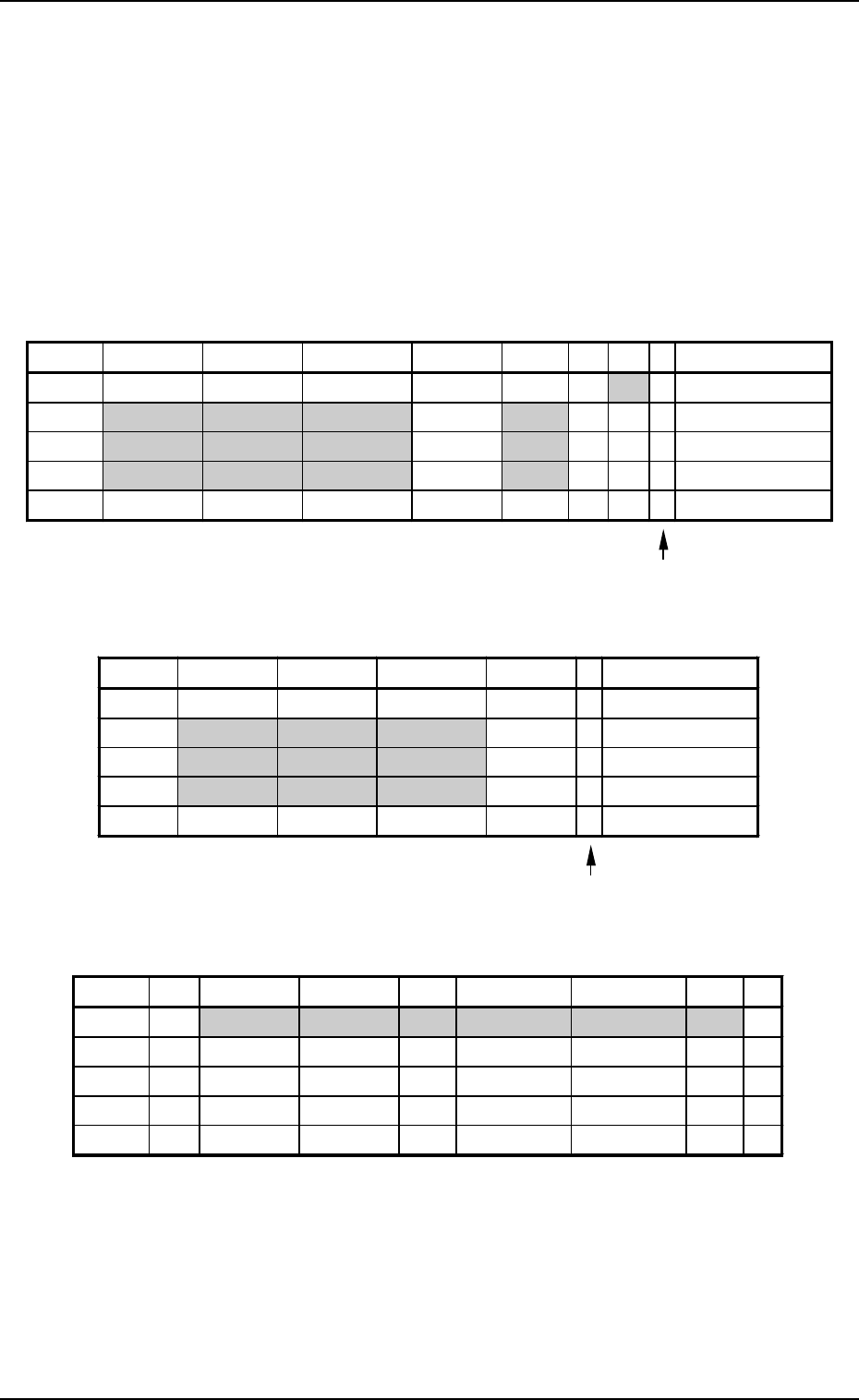
(2) Example of Data Creation
• Use the following placement data.
Placement Data (P) U01, (O) U01, and (V) U01
(P) U02, (O) U02, and (V) U02
(P) U03, (O) U03, and (V) U03
• P.E.C. recognition must be specified for each individual repetitive pat-
terns in the operation data.
Set “ON” in the “P.E.C. RECOGNITION” and “ON” in the “IMAGE”
data box of the label “P.E.C. RECOGNITION MODE”.
Note: Data for Model C must be created as repetitive pattern for one unit
P.C.B. because the P.E.C. recognition function (global) is implemented
according to the repetitive pattern program data created for a unit P.C.B.
Plecemnt Data (P) U01
9910-001 2-85 Tg0247-PM-PM
Enter “0” (zero) in all data fields of the last step and “P” or
“Q” as a control command.
Fig. 2.65
Plecemnt Data (O) U01
Enter “0” (zero) in all data fields of the last step and “E” as
a control command.
Fig. 2.66
Plecemnt Data (V) U01
Fig. 2.67
Notes: (a) The mark code Nos. registered in the “MARK DATA” data boxes
at the “OPERATION DATA” display must be entered in the “F1”
and “F2” data fields.
(b) V-0001, V-0002, V-0003 ... These Nos. correspond to the place-
ment steps.
Do not enter any parameter unless the marks at the placement
position for each individual components should be recognized.
P-NO. X(mm) Y(mm) Z(THETA) H(mm) FDR S V C COMMENT
0000 +0.00 +0.00 +0
°
00’ +0.00 000 - 02 -
0001 +5.00 +20.00 +0
°
00’ +0.00 101 - 00 -
0002 +15.00 +10.00 +180
°
00’ +0.00 201 - 00 -
0003 +25.00 +10.00 +90
°
00’ +0.00 301 - 00 -
0004 +0.00 +0.00 +0
°
00’ +0.00 000 - 00 P
O-NO. X(mm) Y(mm) Z(THETA) H(mm) C COMMENT
0000 +0.00 +0.00 +0
°
00’ +0.00 -
0001 +5.00 +5.00 +0
°
00’ +0.00 -
0002 +35.00 +5.00 +0
°
00’ +0.00 -
0003 +65.00 +5.00 +0
°
00’ +0.00 -
0004 +0.00 +0.00 +0
°
00’ +0.00 E
V-NO. V X1(mm) Y1(mm) F1 X1(mm) Y1(mm) F2 C
0000 02 +5.00 +5.00 01 +25.00 +25.00 01 -
0001 00 +0.00 +0.00 00 +0.00 +0.00 00 -
0002 00 +0.00 +0.00 00 +0.00 +0.00 00 -
0003 00 +0.00 +0.00 00 +0.00 +0.00 00 -
0004 00 +0.00 +0.00 00 +0.00 +0.00 00 P