2OM-1064-002.pdf - 第181页
P0 Y (+) X (+) Fee de r Ba se #1 Beam B Side Teaching Plate Se ction Refe rence Point: “F ront” Teaching Plate S ection Refe rence Point: “Rear” Fee de r Ba se #2 Fee de r Ba se #3 Fee de r Ba se #4 Beam A Side PL -X Y C…
Third Page
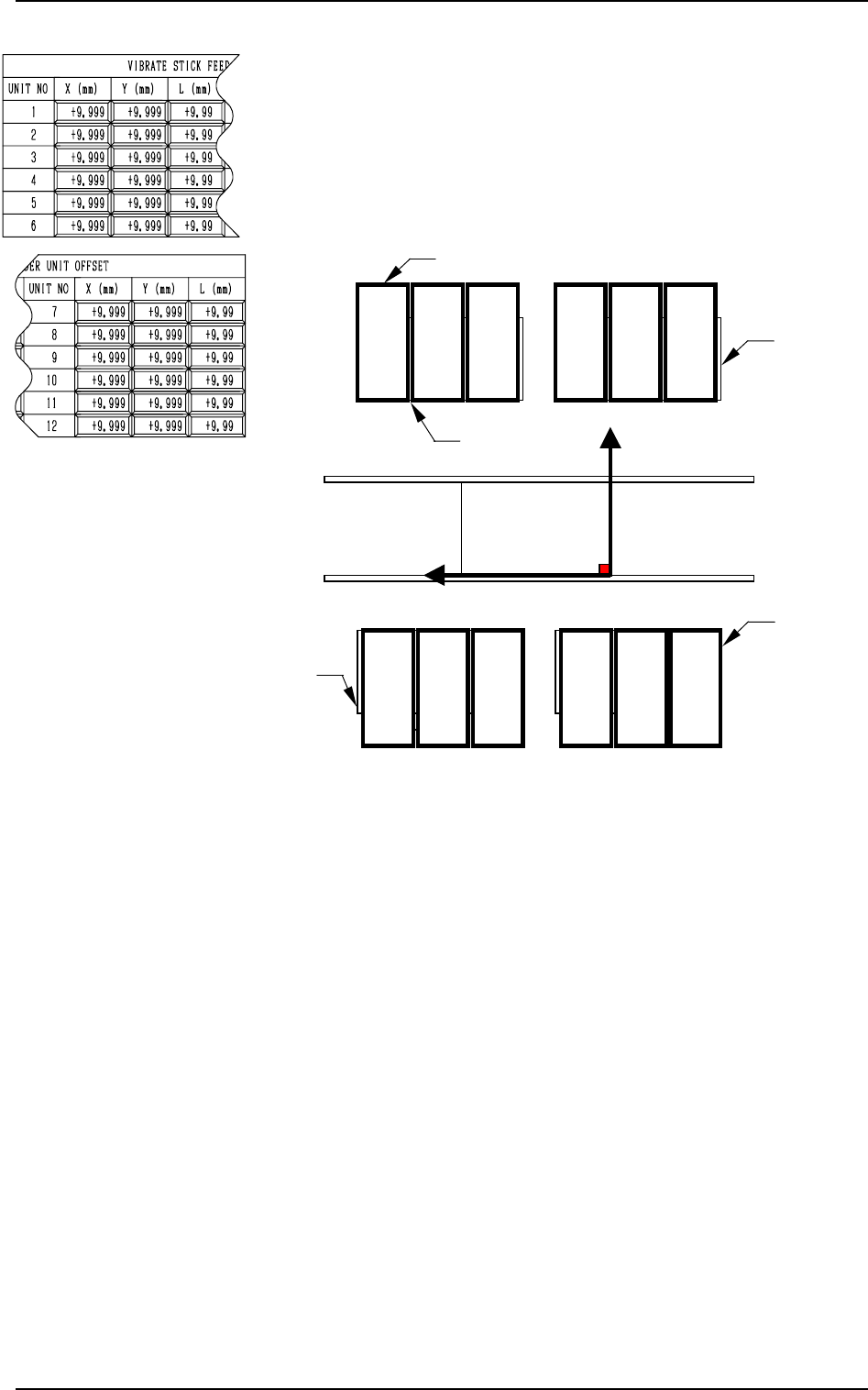
VIBRATE STICK FEEDER UNIT OFFSET X (mm), Y (mm)
The set offset parameters are used to adjust the positional de-
viations based on the design dimensions of Vibratory Stick
Feeder Units #1 through #12 (#4 through #12 are optional).
The values based on the PL-XY coordinate system must be
entered in the data boxes.
Ref.: The manual alignment teaching operation is possible.
0004-002 5-10 Tg0247-PM-PM
2. DEVICE OFFSET Display
P0
Y(+)
X
(+)
PL-XY Coordinate System
Feeder Base #2
Feeder Base #3
Feeder Base #4
(Front Side of Machine)
12
3
45
6
12 11
10
9
8
7
Vibratory Stick Feeder Units
Feeder Base #1
Fig. 5.8
When offset parameters are entered with “+” (plus) signs for
“X (mm)” and “Y (mm)”, the X/Y head moves in the (+) di-
rection in the PL-XY coordinate system.
VIBRATE STICK FEEDER UNIT OFFSET L (mm)
The set offset parameters are used to adjust the vertical (height
direction) deviations based on the design dimensions of Vi-
bratory Stick Feeder Units #1 through #12 (#4 through #12
are optional).
When a vibratory stick feeder unit is installed lower than the
design value, plus values must be entered.
Ref.: When the [TEACHING] key *1 is pressed, the “UNIT
MANUAL ALIGNMENT TEACH” display appears
on the screen.
P0
Y (+)
X (+)
Feeder Base #1
Beam B Side
Teaching Plate Section
Reference Point: “Front”
Teaching Plate Section
Reference Point: “Rear”
Feeder Base #2
Feeder Base #3
Feeder Base #4
Beam A Side
PL-XY Coordinate System
Fourth Page
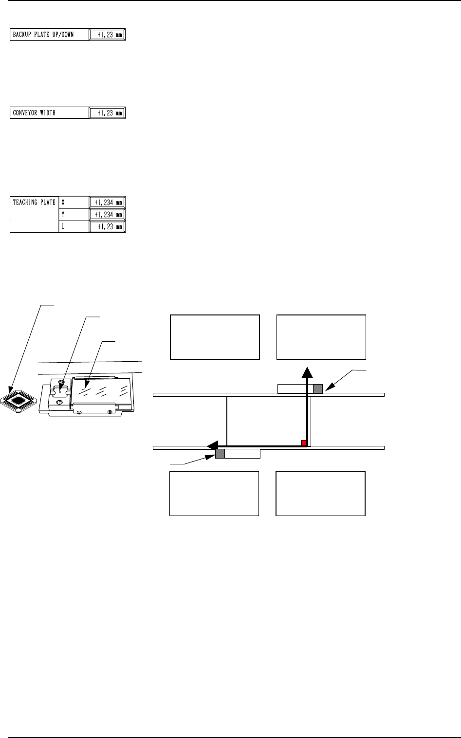
BACKUP PLATE UP/DOWN
This is the offset data for the origin position of the backup
plate up/down axis which ascends or descends during P.C.B.
positioning.
A plus (+) value decreases the ascending stroke during P.C.B.
positioning.
CONVEYOR WIDTH
This is the offset data to adjust the absolute value for the con-
veyor width. Enter the difference between the actually mea-
sured width and the data width caused when the conveyor width
is set up to the width specified by a parameter.
When the actually measured width is narrower than the width
specified by a parameter, a plus value must be entered.
TEACHING PLATE X, Y
The set offset parameters are used to adjust the positional de-
viations based on the design dimensions of the teaching plate
(the glass jig used for automatic teaching operation of various
offset data) stock position. The values based on the PL-XY
coordinate system must be entered in the data boxes.
Note: The teaching plate section differs according to the ref-
erence position of the machine.
Ref.: The manual alignment teaching operation is possible.
Teaching Plate Section
0004-002 5-11 Tg0247-PM-PM
2. DEVICE OFFSET Display
Fig. 5.9
When offset parameters are entered with “+” (plus) signs for
“X (mm)” and “Y (mm)”, the X/Y head moves in the (+) di-
rection in the PL-XY coordinate system.
TEACHING PLATE L
The set offset parameter is used to adjust the vertical (height
direction) deviation based on the design dimension of the teach-
ing plate (the glass jig used for automatic teaching operation
of various offset data) stock position.
When the teaching plate is installed lower than the design value,
a plus value must be entered.
Ref.: When the “X”, the “Y”, or the “L” data box of the
label “TEACHING PLATE” is selected, the [TEACH-
ING] key appears at *1.
When this key is pressed, the “UNIT MANUAL ALIGN-
MENT TEACH” display appears on the screen.
Teaching Plate
Teaching Plate
Stock Position
Back Light
Stage
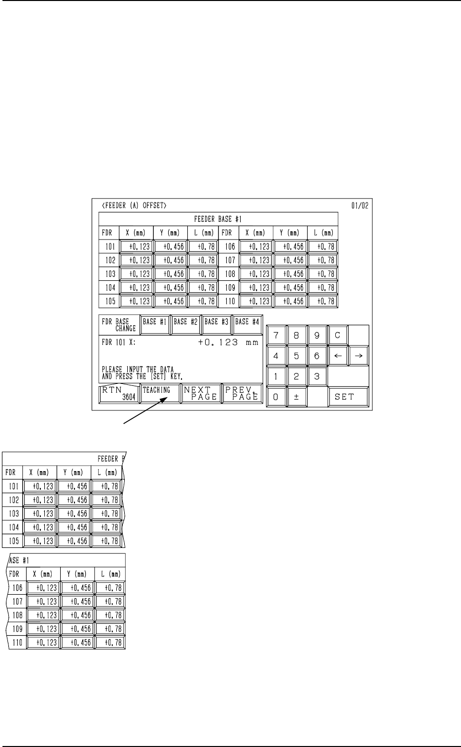
Fig. 5.10
FEEDER (A) OFFSET X (mm) and Y (mm)
The feeder (A) offset data is used to adjust the positional de-
viation based on the design dimensions representing the com-
ponent pick-up position for each individual feeder slot Nos.
(FDR. NO.).
The values based on the PL-XY coordinate system must be
entered in the data boxes.
These parameters must be measured, using the master jig and
set as the data for positional alignment with each feeder’s com-
ponent pick-up position.
Ref.: The manual alignment teaching operation is possible.
*1
3. FEEDER (A) OFFSET and FEEDER (B) OFFSET Displays
3. FEEDER (A) OFFSET and FEEDER (B) OFFSET
Displays
• The feeder (A) offset data is used independently for the machine and repre-
sents the feeder’s component pick-up position indicated by each individual
feeder slot Nos. (FDR. NO.).
• The feeder (B) offset data is used to correct the variation in each feeder to be
installed.
When the [FEEDER (A) OFFSET] key is pressed at the “OFFSET DATA”
display, the following display appears on the screen.
9910-001 5-12 Tg0247-PM-PM