2OM-1064-002.pdf - 第44页
Fig. 2.29 [PROGRAM CHECK] Key When this key is pressed, the edited pattern program is checked. CONVEYOR WIDTH Set one of the followings in the data box to determine whether or not the conveyor width should be set up auto…
Range between Lines
and Tangential Lines
1/3 of Shorter Side
0.5 to 2.0
0.5 to 2.0
0.5 to 2.0
0.5 to 2.0
1/3 of Shorter Side
Range between Lines
and Tangential Lines
0.5 to 1.5
1.0 to 2.0
Min. 0.25
80° (Range
between Lines
and Tangential
Lines)
(Front Side of Machine)
45°
Pad Mark 45°
Range of Land Location
in Increments of 45° for
Pad mark
Pad Mark 90°
Range of Land Location
in Increments of 90° for
Pad mark
Range of Land Location
for Through Hole
(45° at the bottom right
of the hole)
Examples of Land
Locations
(Front Side of Machine)
(Front Side of Machine)
(Front Side of Machine)
2. Pattern Program
(2) Material
• Copper Leaf
(Au and Ni plating possible but mirror surfaces cannot be used.)
• Solder Plating (Consult our sales personnel.)
• Solder Leveler (Consult our sales personnel.)
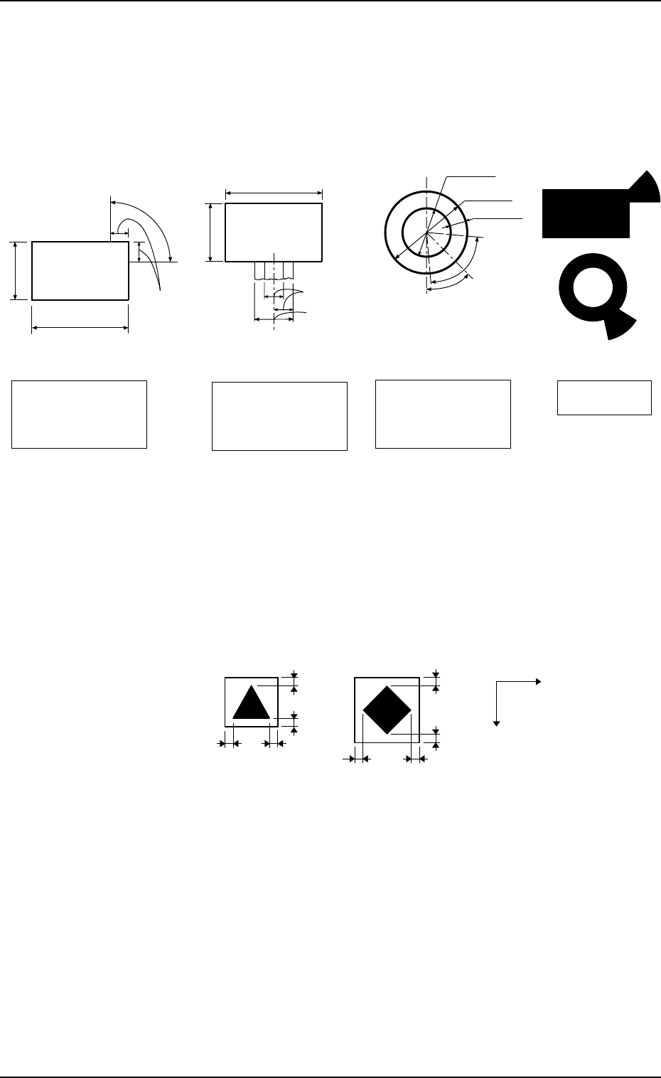
(3) Specifications of Lines extended from a Pad Mark or a Through Hole
(Unit: mm)
1.0
X
Y
1.0
1.0
1.0
1.01.0
1.0
1.0
Unit: mm
(Front Side of Machine)
Example:
Fig. 2.28
(c) The shape of P.C.B. (a cutout, a punched hole), the exter-
nal elements (light reflected from a structure, light emitted
from an external device, etc.) may sometimes interfere with
recognition. Consult our sales personnel for details.
(d) A fiducial mark should make ample contrast with the sur-
roundings. (To prevent false recognition)
(e) Anything resembling a pattern similar to a fiducial mark
should not exist in the designated window. If one exists, it
may cause false recognition.
(f) A test may be required when the fiducial mark cannot be
recognized because of the extreme warpage of the P.C.B.
Fig. 2.27
Notes: (a) A through hole or a pad mark should have only one land
which is directed in increments of 45°. Consult our sales
personnel for details (dimensions, etc.).
(b) A copper leaf, a resist, a coating, a silk print, and a punched
hole should not exist in the range of 1.0 mm in both X and
Y directions from the outermost edges of a fiducial mark.
They may cause false recognition.
9910-001 2-31 Tg0247-PM-PM
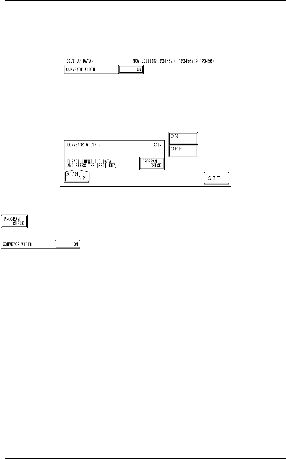
Fig. 2.29
[PROGRAM CHECK] Key
When this key is pressed, the edited pattern program is checked.
CONVEYOR WIDTH
Set one of the followings in the data box to determine whether
or not the conveyor width should be set up automatically.
“ON”
“OFF”
When the pattern program for which “ON” is set is changed
by pressing the [MOVE] button, the conveyor width is auto-
matically set up and changed in accordance with the param-
eter set in the “Y (vertical)” data box of the label “P.C.B. SIZE”
at the “OPERATION DATA” display.
2.4 SET-UP DATA Display
When the [SET-UP DATA] key is pressed at the “PATTERN PROGRAM
EDIT” display, the following display appears on the screen.
2. Pattern Program
9910-001 2-32 Tg0247-PM-PM
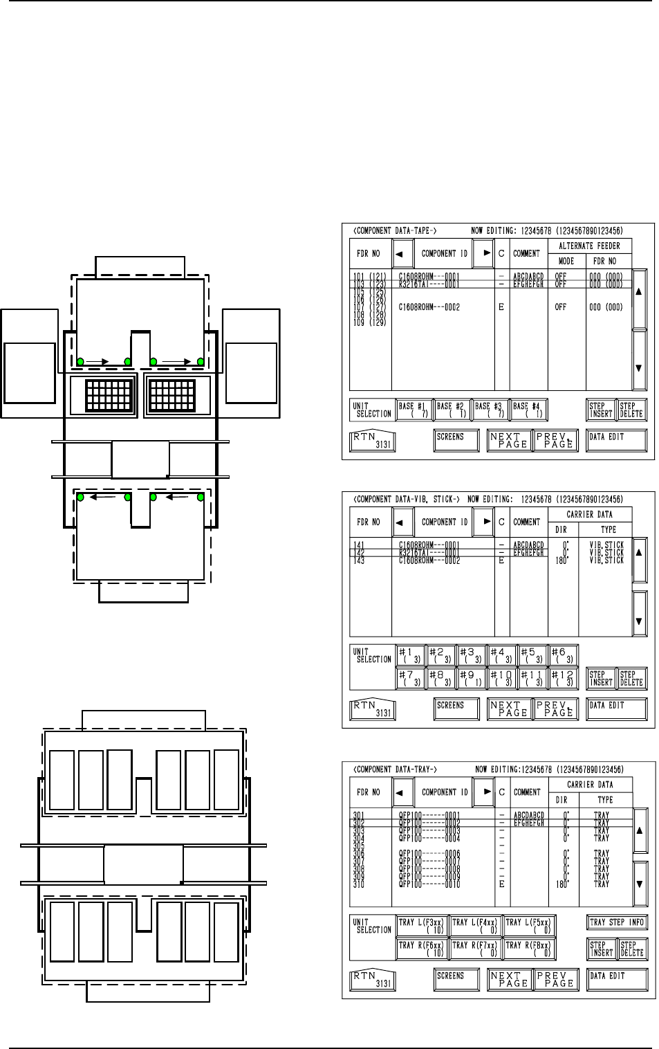
2.5 COMPONENT DATA Display
When the [TAPE [A] (F101-F139)], the [VIB STICK [A] (F141-F199)], or the
[TRAY L (F301-F599)] key is pressed at the “PATTERN PROGRAM EDIT”
display, the corresponding display (Fig. 2.31, 2.32, or 2.33) appears on the
screen.
When the [TAPE [B] (F201-F239)], the [VIB STICK [B] (F241-F299)], or the
[TRAY R (F601-F899)] key is pressed, the corresponding display (similar to
Fig. 2.31, 2.32, or 2.33) appears on the screen.
For Tape Feeders
701 to799
801 to899
FDR 101 to 139
101…119 121…139
Feeder
Base
2
FDR
239 to 201
Beam A
Multi-Layer
T
ray Feeder L
(Option)
601 to699301 to 399
401 to 499
501 to 599
219
…
201
239
…
221
Multi-Layer
Tray Feeder R
(Option)
The numbers represent feeder Nos. (FDR NO).
Beam B
Feeder
Base
1
Feeder
Base
3
Feeder
Base
4
Feeder
Base A
Feeder Base B
Fig. 2.30-1
Fig. 2.33
Fig. 2.32
Fig. 2.31
[TEAP A]
[VIB. STICK A]
[TRAY L]
FDR 141 to 199
FDR 299
to
241
Beam B
141
149
to
Feeder Base 1
151
159
161
169
171
179
181
189
191
199
261
269
251
259
241
249
291
299
271
279
281
289
Feeder Base 2
Feeder Base 3Feeder Base 4
Beam A
For Vibratory Stick Feeders
to
to
to
to
to
to
to
to to
to
to
Feeder Base A
Feeder Base B
Fig. 2.30-2
2. Pattern Program
0004-002 2-33 Tg0247-PM-PM