2OM-1064-002.pdf - 第219页
COMPONENT STORAGE BOX-B X (Horizontal), Y (V erti- cal), L (Height) This offset data is used to adjust the positional (horizontal) and vertical (height direction) deviations, compared with the design dimensions (position…
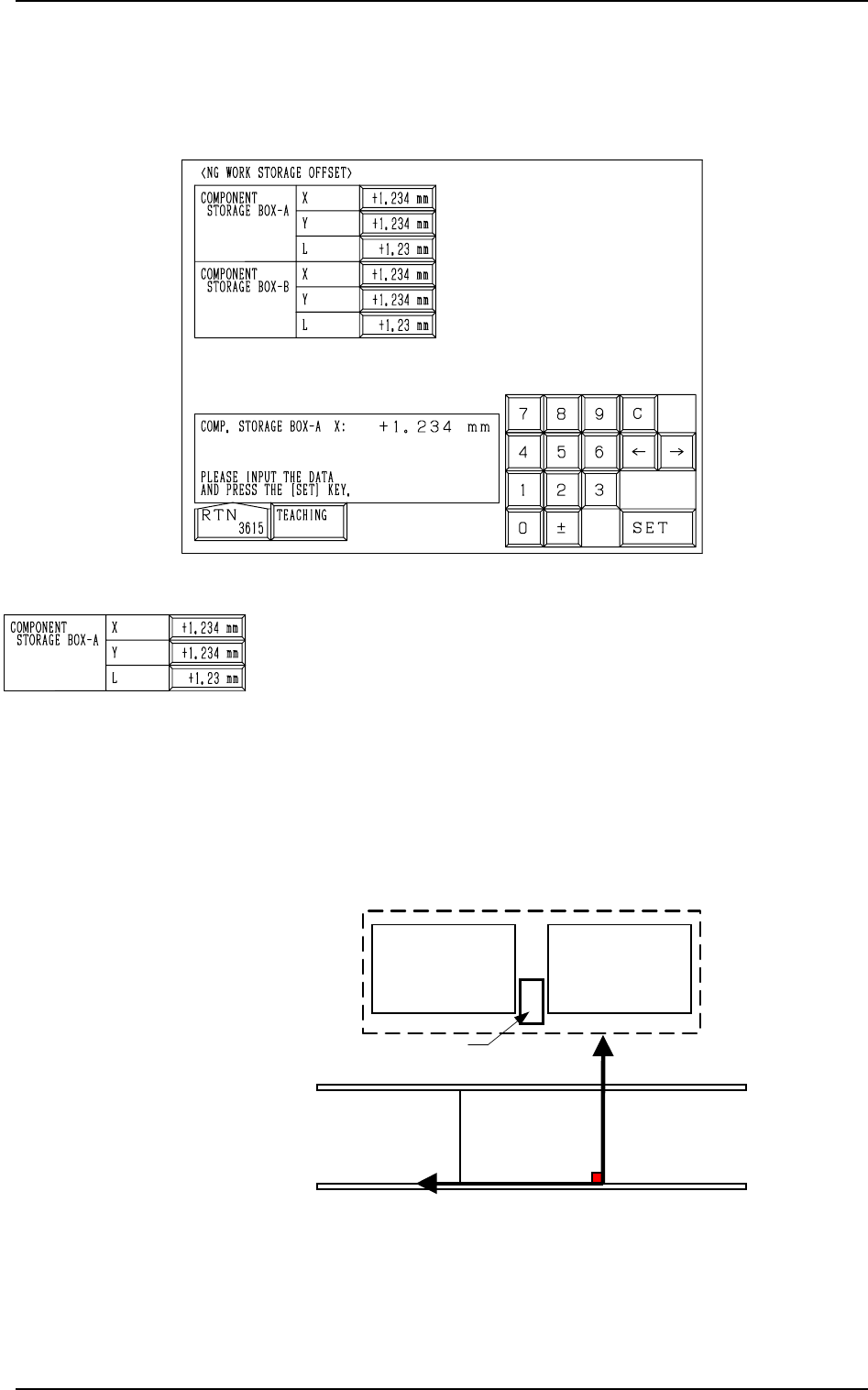
Fig. 5.43
COMPONENT STORAGE BOX-A X (Horizontal), Y (Verti-
cal), L (Height)
This offset data is used to adjust the positional (horizontal)
and vertical (height direction) deviations, compared with the
design dimensions (position) of the component storage box
located between the right and left feeder bases on the beam A
side. This offset data must be set based on the PL-XY coordi-
nate system.
The component storage box is used to store the rejected com-
ponents in the component recognition processing.
0004-002 5-48 Tg0247-PM-PM
15. NG WORK STORAGE OFFSET Display (Option)
When the [COMPONENT REJECT OFFSET] key is pressed at the “OFFSET
DATA” display, the following display appears on the screen.
15. NG WORK STORAGE OFFSET Display (Option)
PL-XY
Coordinate System
PO
Feeder Base #1
Component Storage Box A
Y
(+)
X
(+)
Feeder Base #2
Feeder Base A
Fig. 5.44
When Component Storage Box A is shifted toward the upper
left direction (viewed from the top), plus values must be en-
tered in the “X (Horizontal)” and “Y (Vertical)” data boxes.
When the level (height) of the box is set lower than the design
value, a plus value must be entered in this data box.
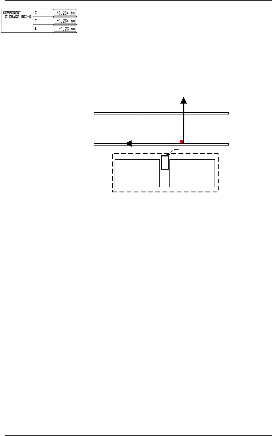
COMPONENT STORAGE BOX-B X (Horizontal), Y (Verti-
cal), L (Height)
This offset data is used to adjust the positional (horizontal)
and vertical (height direction) deviations, compared with the
design dimensions (position) of the component storage box
located between the right and left feeder bases on the beam B
side. This offset data must be set based on the PL-XY coordi-
nate system.
The component storage box is used to store the rejected com-
ponents in the component recognition processing.
0004-002 5-49 Tg0247-PM-PM
15. NG WORK STORAGE OFFSET Display (Option)
PL-XY
Coordinate System
PO
Component Storage Box B
Feeder Base #3
Y
(+)
X
(+)
Feeder Base #4
Feeder Base B
Fig. 5.45
When Component Storage Box B is shifted toward the upper
left direction (viewed from the top), plus values must be en-
tered in the “X (Horizontal)” and “Y (Vertical)” data boxes.
When the level (height) of the box is set lower than the design
value, a plus value must be entered in this data box.
BEAM A HEAD #1
CAM-A1 X (Horizontal), Y (Vertical)
These offset parameters indicate the positional deviations
of the head rotational center compared with the center of
Camera A1 when Head #1 on Beam A faces Camera A1 as
a subordinate head. The parameters are set based on the
camera scanning coordinate system of the component rec-
ognition camera.
CAM-B2 X (Horizontal), Y (Vertical)
These offset parameters indicate the positional deviations
of the head rotational center compared with the center of
Camera B2 when Head #1 on Beam A faces Camera B2 as
a subordinate head. The parameters are set based on the
camera scanning coordinate system of the component rec-
ognition camera.
9910-001 5-50 Tg0247-PM-PM
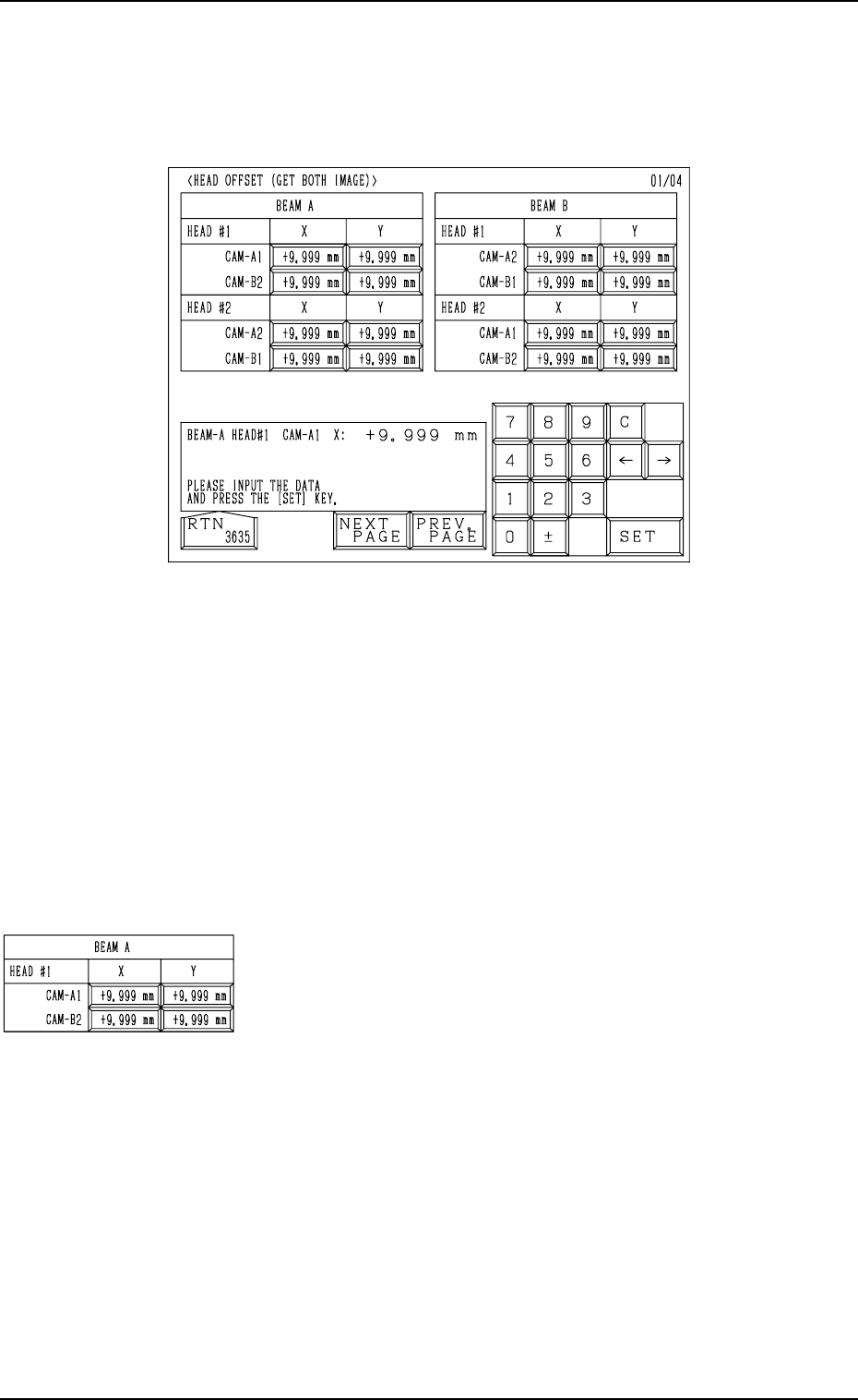
16. HEAD OFFSET (GET BOTH IMAGE) Display
16. HEAD OFFSET (GET BOTH IMAGE) Display
When the [HEAD OFFSET (GET BOTH IMAGE)] key is pressed at the “OFF-
SET DATA” display, the following display appears on the screen.
Fig. 5.46
When steps are paired through the simultaneous pick-up or the pick-up prior-
ity function designated in the placement data, the component recognition func-
tion (simultaneous recognition function) is implemented with components be-
ing picked up by both right and left heads. At this time, this offset data indi-
cates where the head rotational center of the subordinate head is located in
comparison with the center of the confronting camera.
When each head on both Beams A and B is used as a subordinate one, the
positional deviations between the center of each head and the centers of the
confronting cameras are determined and set.
These groups of all offset parameters are automatically calculated through teach-
ing operations.